The Results and Interpretation
The results showed that the Energizer inductive power mat does indeed use the physical property of induction to charge a device without the use of wires. This is true and can be observed through the change in the magnetic field from the data we collected.
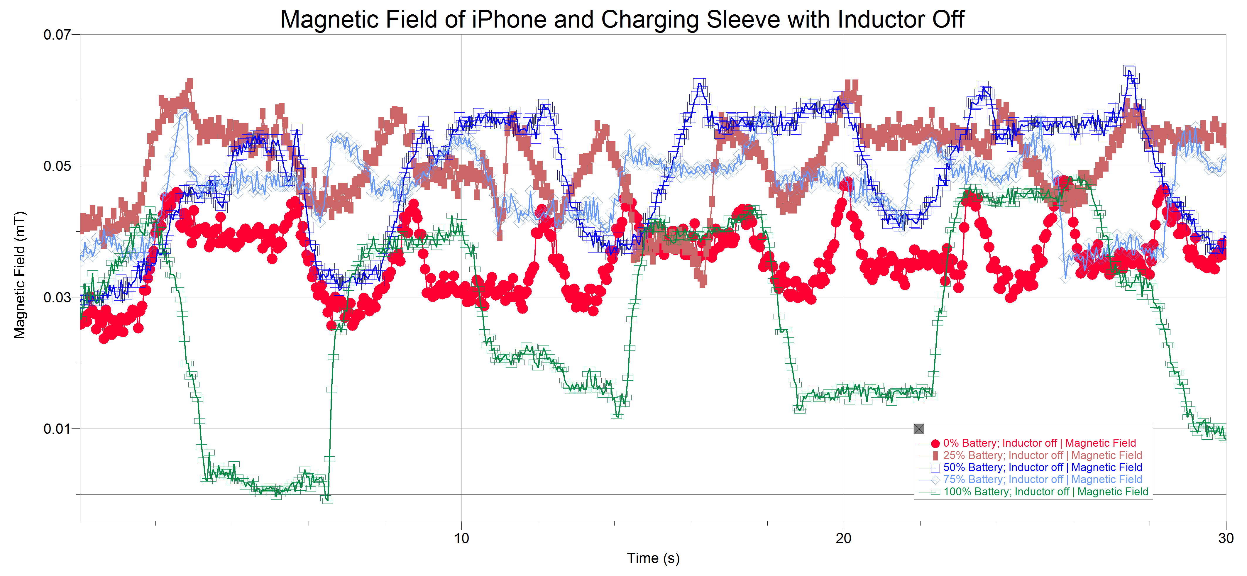
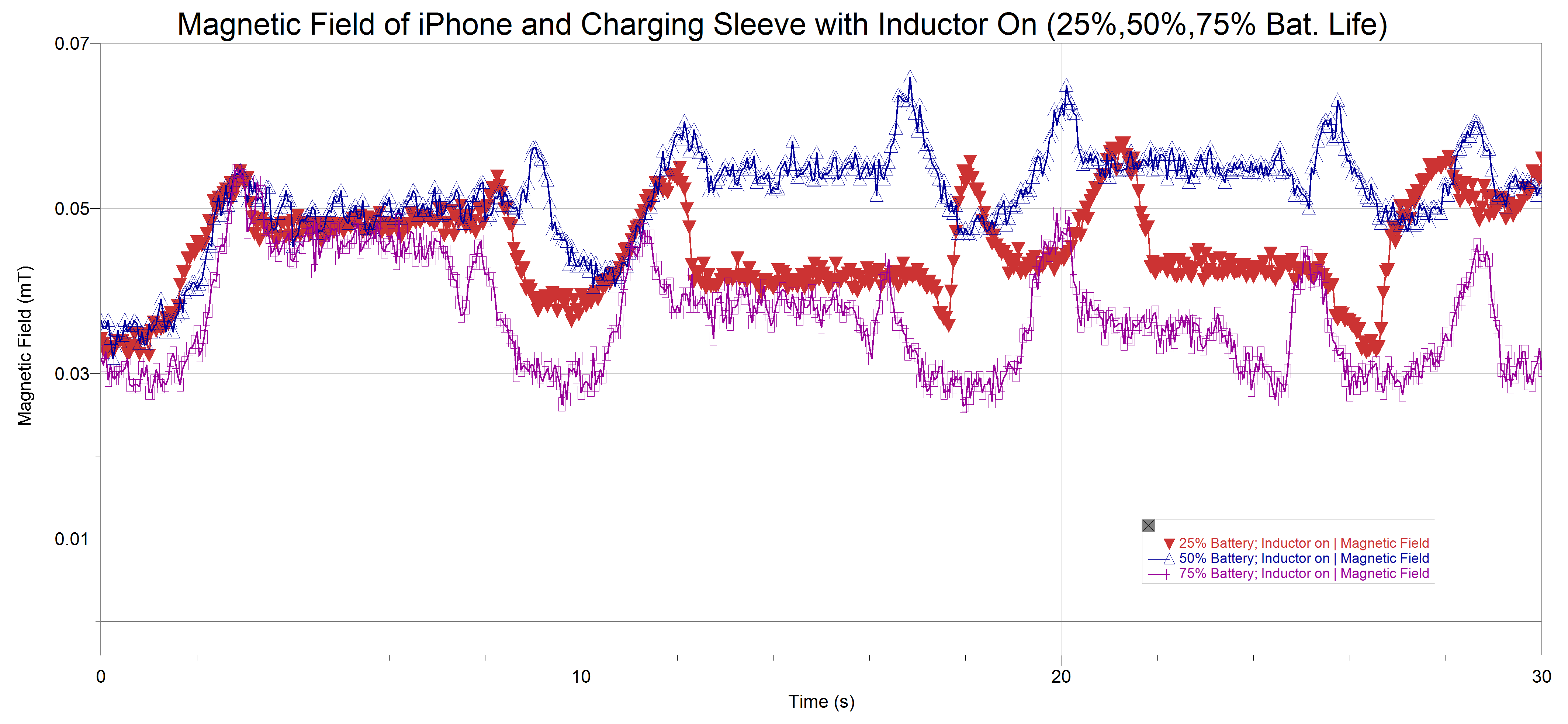
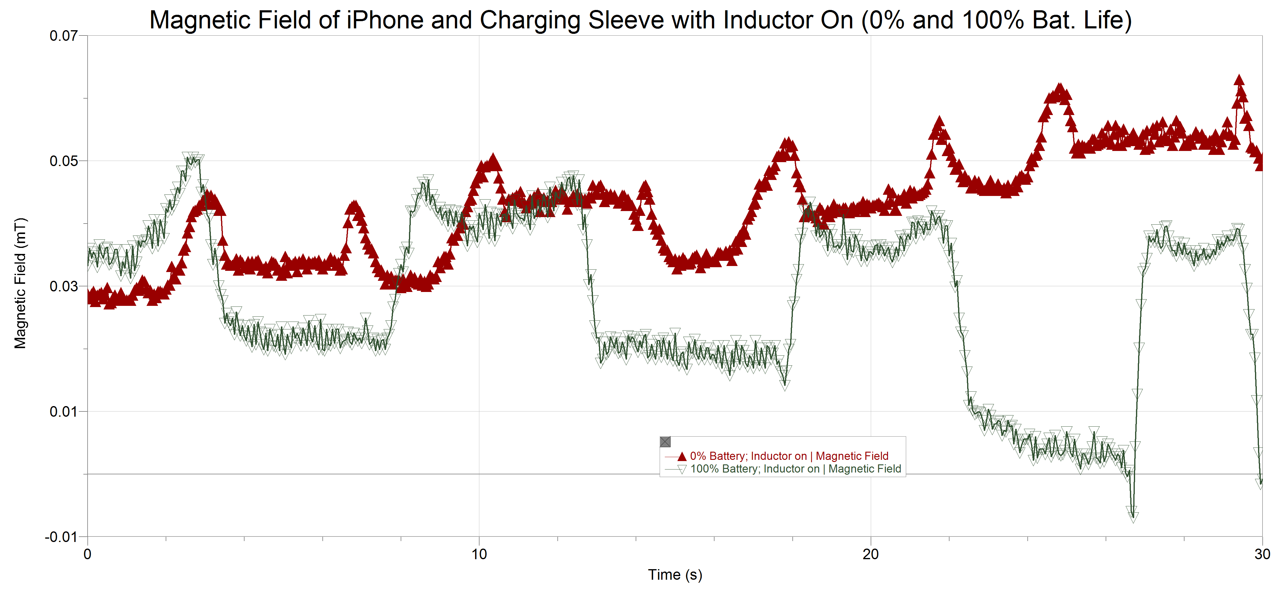
When the battery life of the iPhone is at 0% (approximately 0%) and it is placed and removed from the power mat we observe a sort of sin function over time, the peaks and valleys are due to the motion of the iPhone (because the magnets inside of the phone are moving, they create a change in magnetic field that the sensor picks up). Look at the linear fits applied to the points (see graph below). With the inductor on there is a clear difference from its line and that of the line representing no charging (inductor off). Not only is the field greater but it is also increasing. This illustrates that there is current being induced and that the radio transmitters in the separate devices are communicating successfully to power the phone efficiently, by this I mean that it is trying to supply a large amount of current through a larger changing magnetic field because the phone needs a higher current (later on we’ll see that as the charge on the phone increases this magnetic field will show a negative correlation).
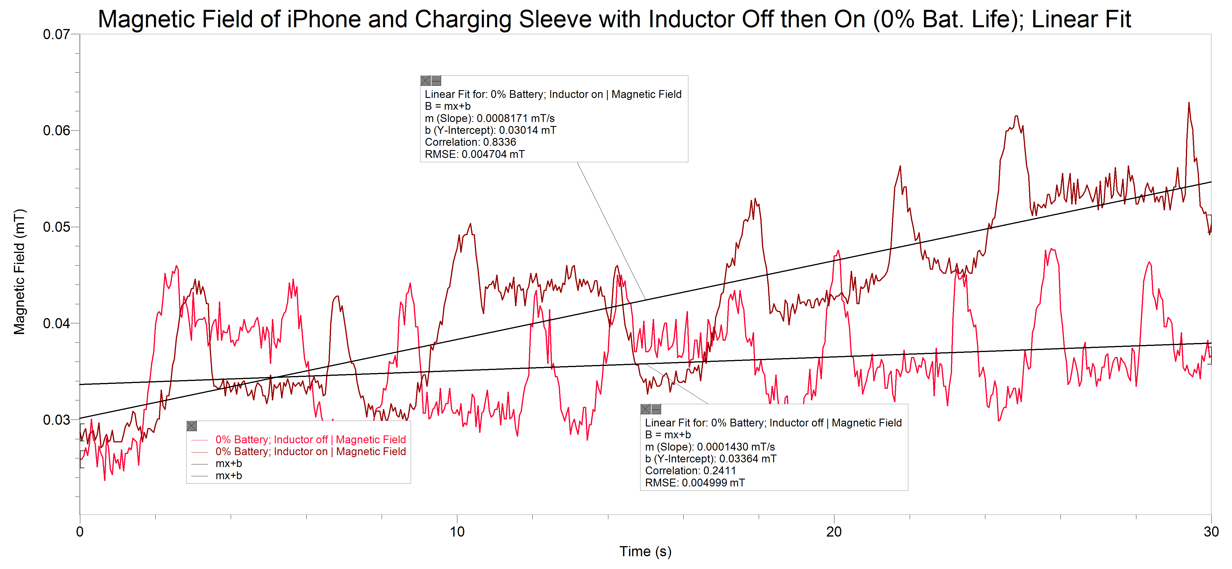
Notice the linear fit to the collection of points representing the iPhone charging on the pad (the darker red) and see how they have a positive correlation. (click on the graph to view details)
The following graphs and liner fits will highlight how the communication between the sleeve and the charger effectively charges the phone, i.e. if the phone needs more current a higher or increasing field can bee observed, it the phones needs less current (if it has more battery life) then a less and/or decreasing field can be observed.
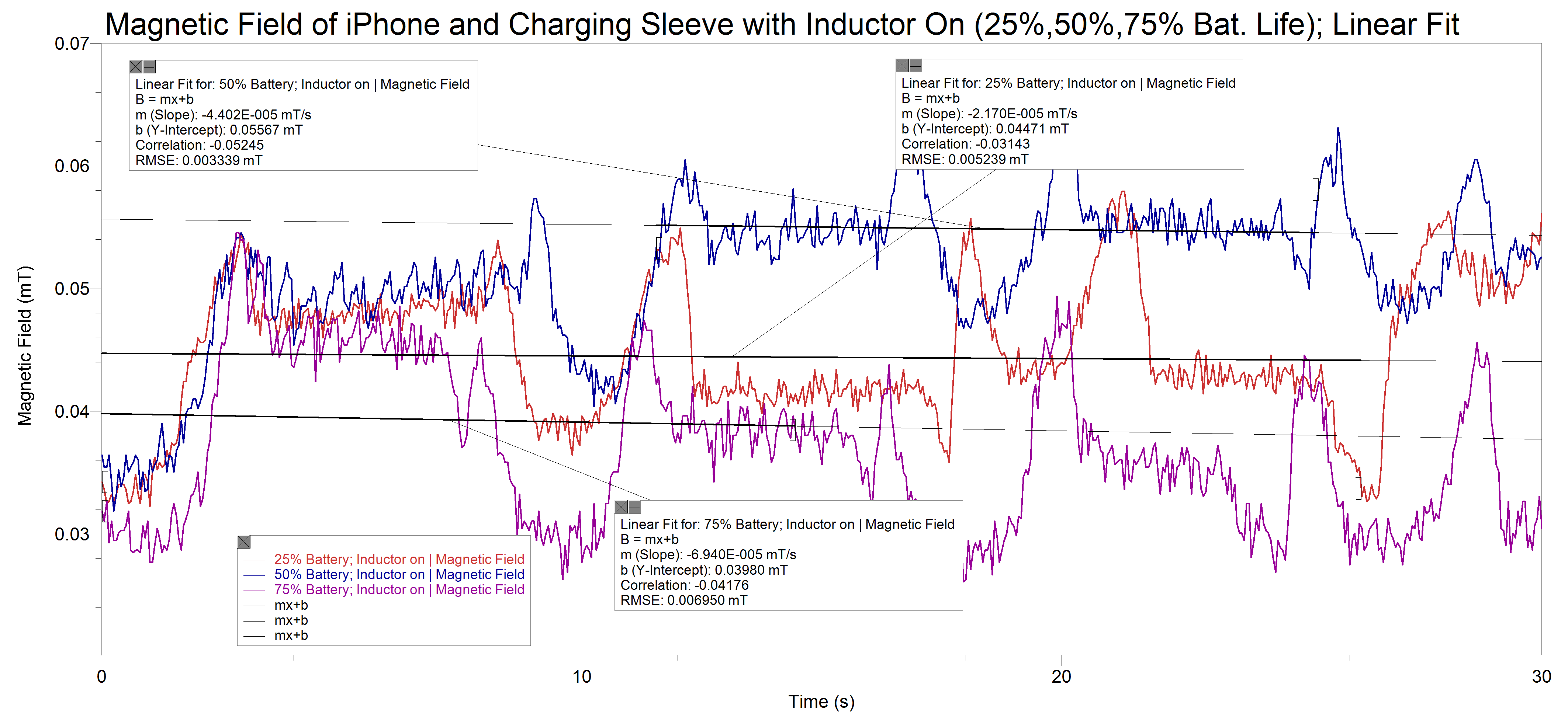
There seems to be a correlation between battery life and magnetic field produced. (click on the graph to view details)
And here again, as the battery life of the phone reaches 100% there is a significant change in the magnitude of the field when it’s charging to when it’s not charging.
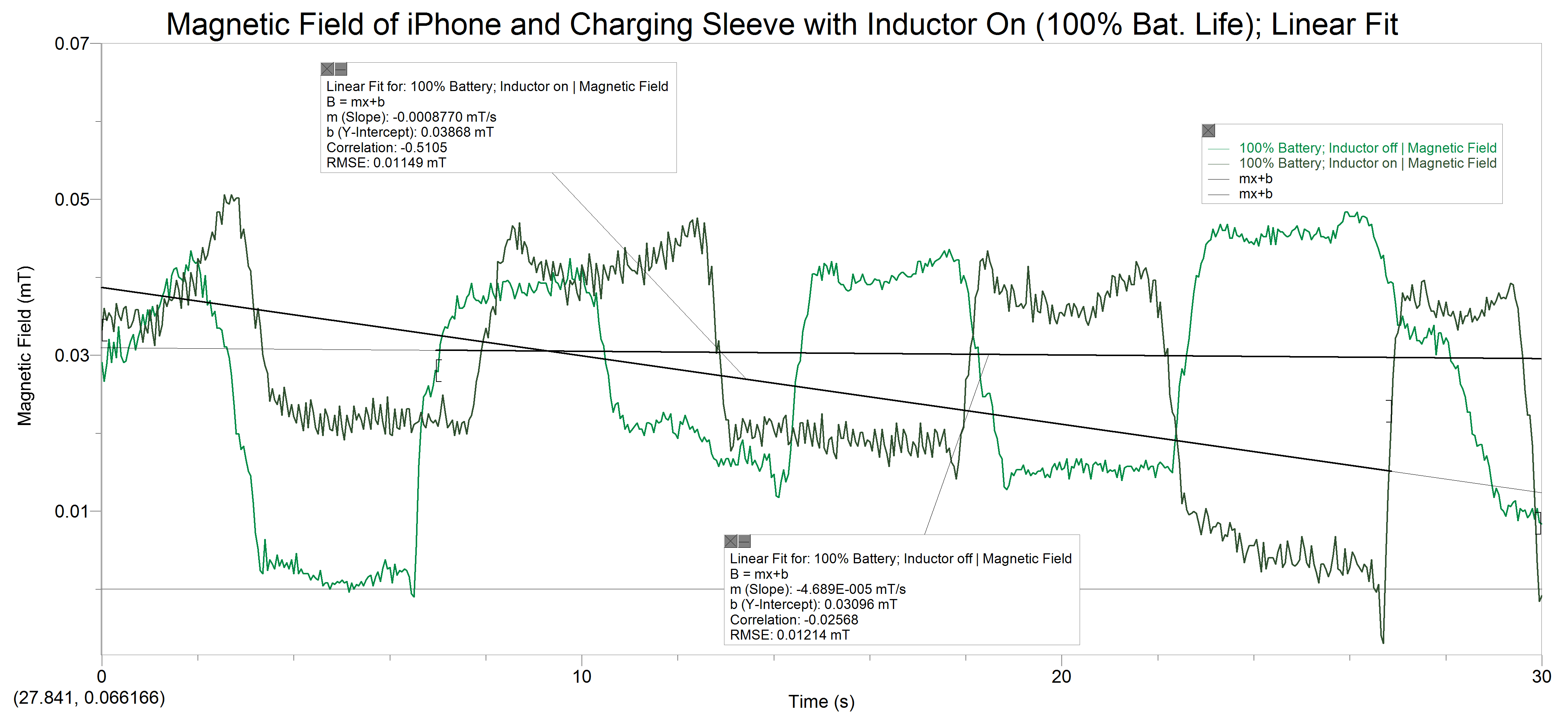
And here an opposite yet expected situation to that of the battery life being at 0%. (click on the graph to view details)
There is an important thing to note in the graph above, the sharp changes in the collection of points representing the not charging state at 100% batter life. In comparison to the other non charging states at different battery life, this one is more drastic (see the graph below). An important detail in science is to recreate an experiment including it’s different trials as similar to all the other trials or experiments. Here I think we have a case of not placing the iPhone in the exact same position as before. As I mentioned earlier we discovered many small magnets dispersed throughout the phone, and during this run we were not being as careful and picked up the magnetic field of one of those magnetic components. Though it does not skew the results significantly, it is important to note.
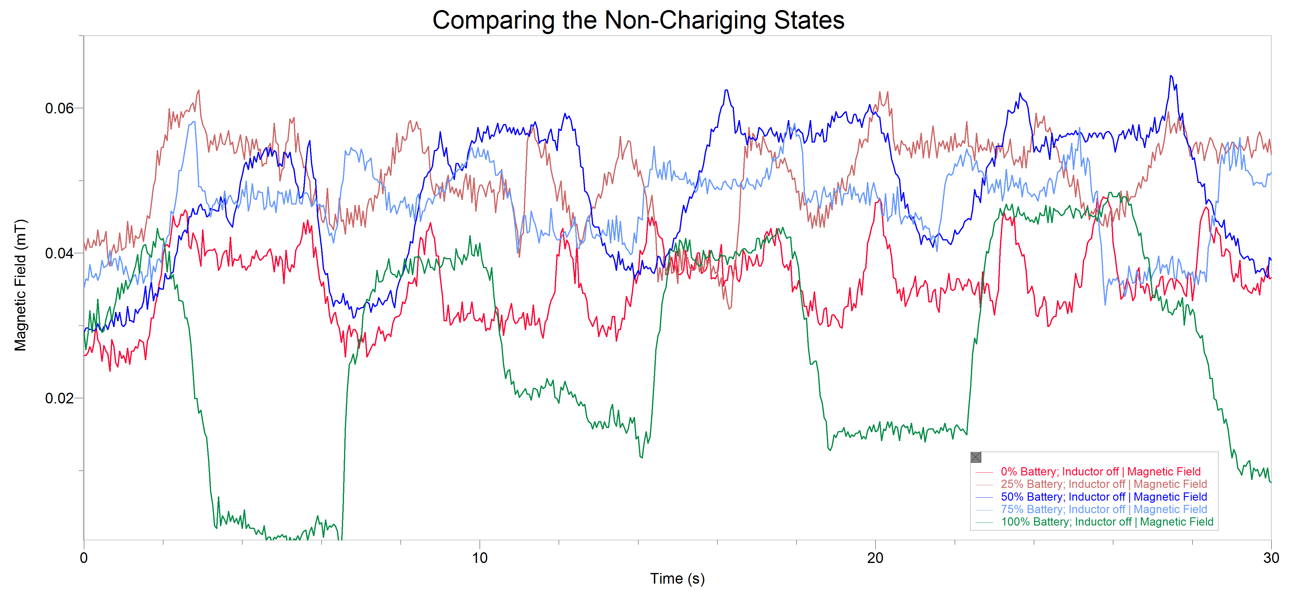
Comparing the non-charging states at different battery life levels. (click on the graph to view details)
Implication of Results
These results mean that indeed the method of induction is a valid method for charging devices but with today’s technology the limitations are clear. The limitations being small distances at which these devices can function. If there were to be some way to transmit greater amounts of power very large coils, very high voltages, and very quickly changing, large magnetic fields would need to be implemented. These larger scaled versions of the induction charger would not only destroy the delicate technology in our current devices but the effects that these instruments would have on the human body would be significant (disruption of electrical powered implants, high risk of electrocution, etc).
Comparing Predictions to Results
We were looking for changes in the magnetic field produced by the charger. We expected that if the battery needed more current then the field would be larger and if it needed less the field would be lesser. Our predictions were correct in that sense, however what we didn’t predict would be how quickly (without a large lagging) the communication between devices happened. The runs are not even a minute long and yet in the 30 seconds of being near the charger, the magnetic field reduces itself for the needed purpose immediately.
The Science at Work
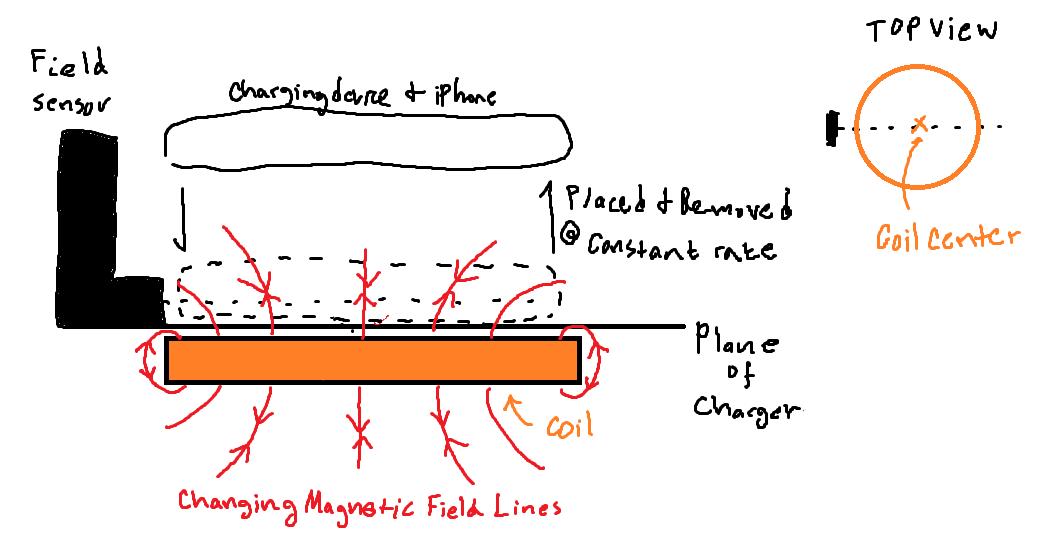
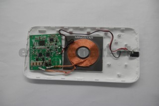
A topic familiar to undergrad physics students, the property of induction is the science this charging device capitalizes on. Electromagnetic induction is a curious and yet obvious result of moving (changing) magnetic fields. Any change in the magnetic environment of a conductor will cause an emf (electromotive force; a force that makes electrons move) to be inducted inside that conductor, in other words, a changing magnetic field can induce current in a wire (read more about induction here). This is due to the fact that electrons have a charge (negative) and are affected by the positive and negative, push and pull of a magnetic field. The way in which a changing magnetic field can be produced is by taking some magnet and literally changing its position in space, however, the way in which the charger creates this alternating field is by running current one way and then running it the opposite direction (alternating the current) this is effective because it can be done rather quickly which also makes needing a very large magnetic field irrelevant (at this scale) it can and does however, increase the field strength when needed by running more current in the primary coil located inside the charger. The coil inside the charger runs an alternating current which then produces a changing magnetic field, this field causes the electrons in the coil inside the charging sleeve to move and create a current. That’s the science behind the charger, which also brings up an interesting idea, that the magnetic field sensor is not measuring just one magnetic field, but many of them and all changing.
What would you differently if you had to do this project again?
The main difference would be to have ordered all the needed materials sooner to have avoided delays in collection.
What would you do next if you had to continue this project for another 6 weeks?
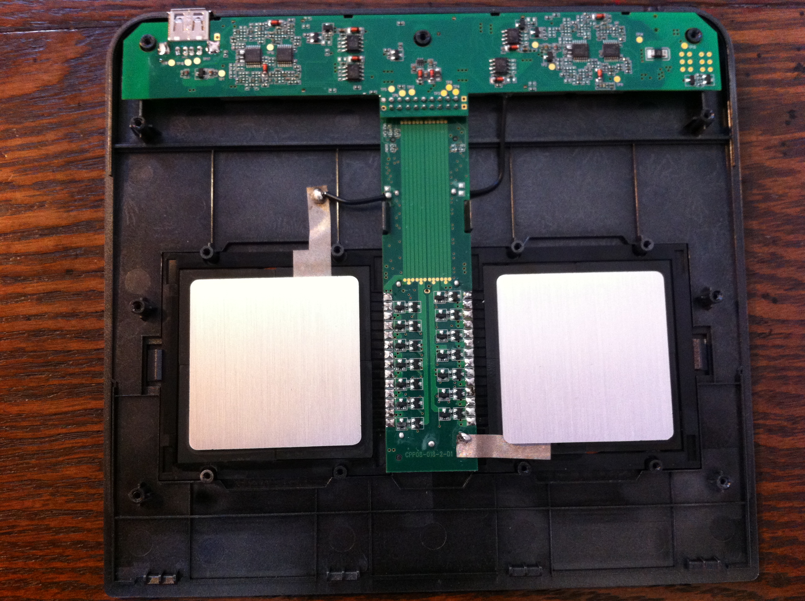
I would have liked to taken apart both devices and left them in their basic forms to both measure more accurately the magnetic fields and also to understand the components that lend themselves to being the necessary technologies to enable the effective transmission of current. And maybe, with that information, even try to imagine a more powerful device.