The Reasoning Behind How Data was Taken
Initially we wanted to measure the magnetic field of the inductive charger by pointing the end of the magnetic field sensor at the center of the charging area, i.e. the center of the induction coil. Unfortunately, due to the distance at which the charging sleeve and inductor communicate (approx 5 mm) it was impossible to get any measurements using this method.
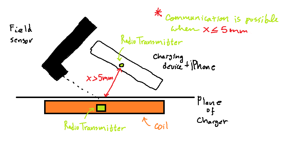
Initial Idea for Experiment Setup (click on image to view details)
Instead, we placed the sensor parallel to the plane of the charging area and pointed the tip towards the center of the coil. This method, although not as accurate as the initial would have been, did manage to produce relevant data of the magnetic field. Aside from a few issues with not being able to measure the actual magnetic field there was one big problem with this method, but one that could be circumnavigated. As we placed the iPhone onto the charger, with the charger unplugged, we noticed that the sensor detected a change in the magnitude of a magnetic field, it turns out that in the iPhone there are a few magnetic components (in different location of the phone) that produce a field comparable to that of a refrigerator magnet. What we did to get around this issue was to, at a steady rate, place and remove the iPhone from the charger while the charger remained unplugged. And, as it turned out, this was also a much better way to measure the field produced by the charger.
The Setup
The experimental setup was to place the sensor parallel to and on the plane of the charger, with the tip pointed towards the center of the coil. Then, to steadily place and remove the iPhone from the charger, paying close attention to placement of the iPhone (this was due to the fact that the magnetic components of the phone were in different locations which could cause discrepancies in the data).
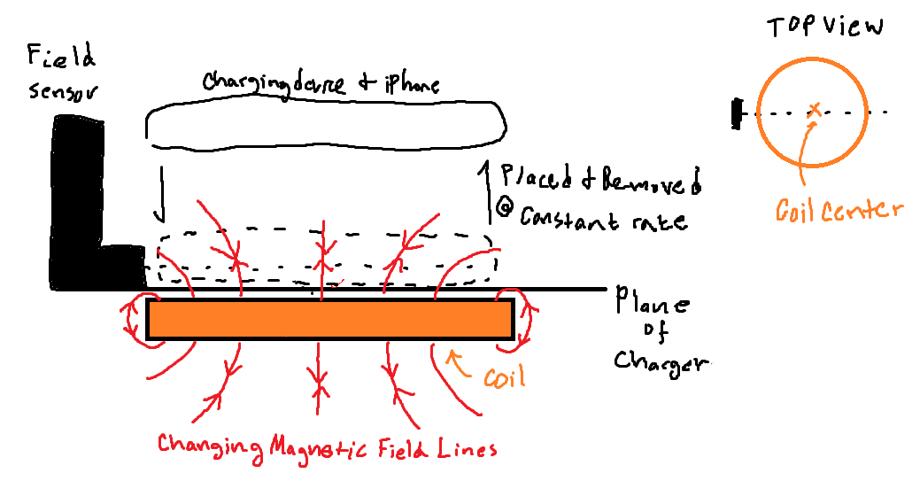
Final Setup for Experiment (click on image to view details)
Initially, this is to be done with the charger unplugged to get a reading of the iPhone’s magnetic field and then with the charger on to see how that field had changed during charging. The trials were done as follows: 0% battery with inductor off, 0% battery with inductor on, 25% battery with inductor off, 25% battery with inductor on, …, 100% battery with inductor off, 100% battery with inductor on.
Data
The data has been organized in the following graphs (note: the units used for measuring the magnetic field are mT or millitesla):
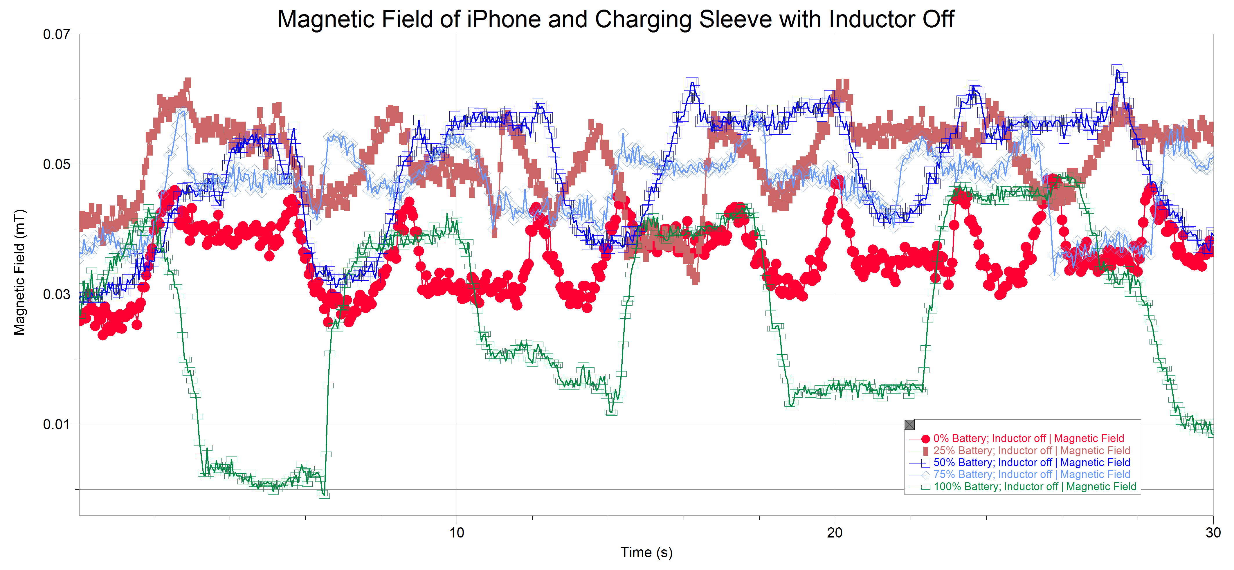
Magnetic Field of the iPhone and Sleeve (click to view details)
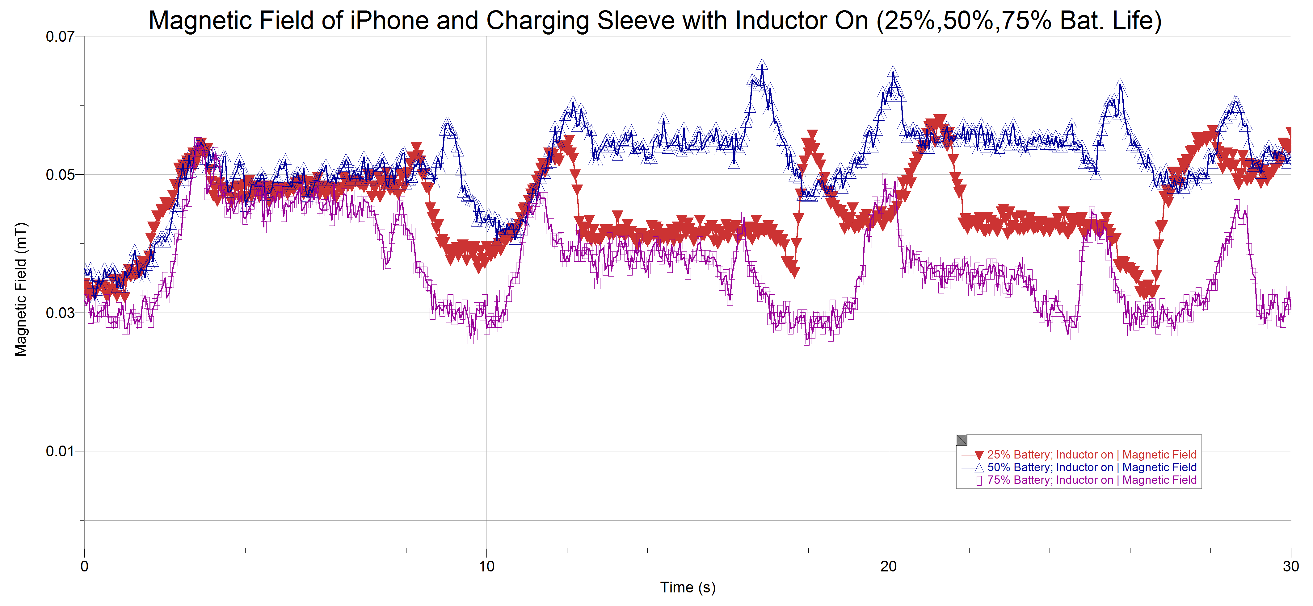
Magnetic Field of iPhone and Charging Sleeve with Inductor On (25,50,75 %. bat. life) (click to view details)
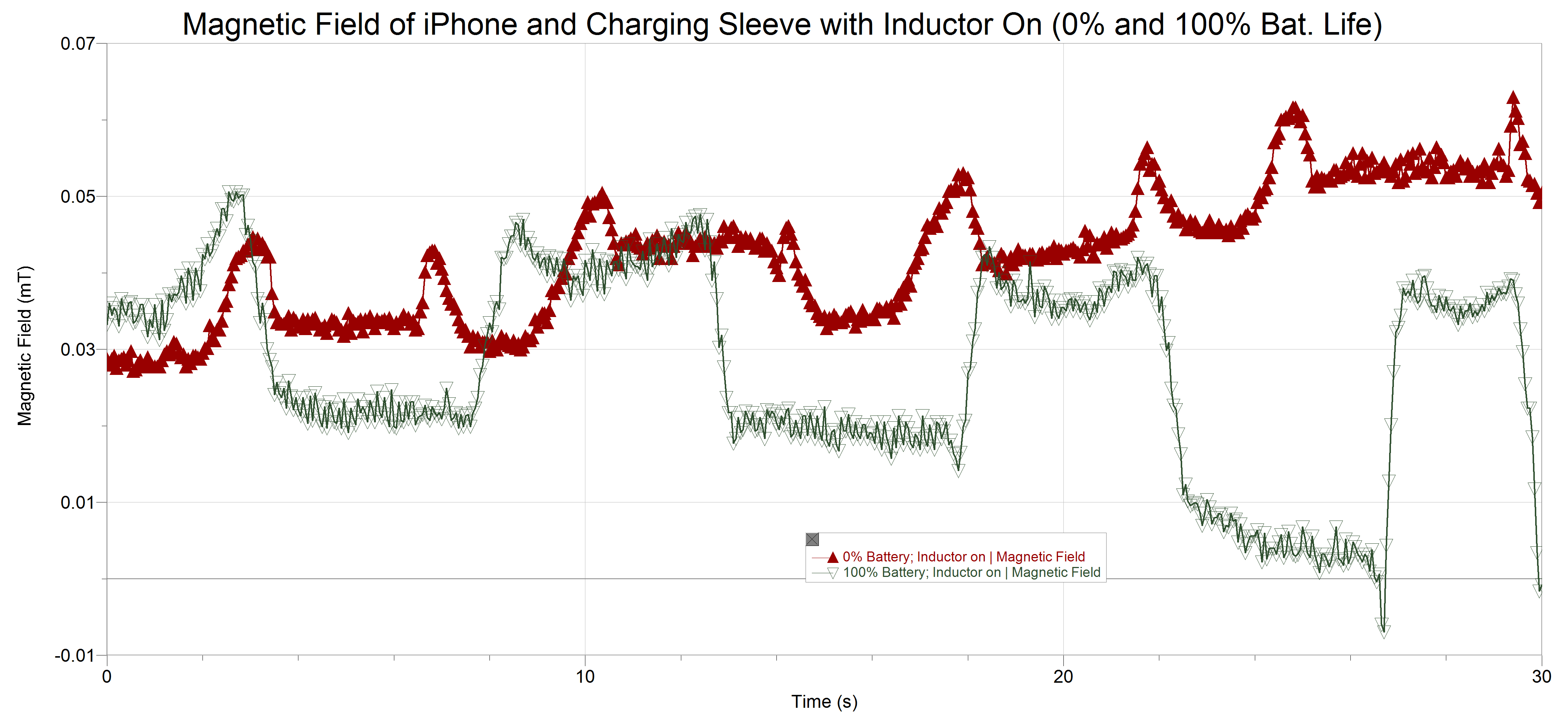
Magnetic Field of iPhone and Charging Sleeve with Inductor On (0% and 100 % bat. life) (click to view details)
Units
As previously mentioned, the unit used in our data collection is the millitesla (One one-thousandths of a tesla) the tesla is the standard unit (SI unit, click here for more info) for measuring magnetic flux density. Flux has to do with the rate at which the magnetic field (in this case) passes through some unit area and density is just how much of the field is passing through the same area, in other words magnetic flux density is the same as saying the magnetic field strength. This unit is named after scientist and inventor Nikola Tesla, not doubt for his contributions in electricity and magnetism. Many of his inventions used magnets to create current, he was also famous for his experiments in wireless power transmission.
Nice induction data. It might be good to explain the unit of measurement, mT.