Author Archives: juvasquez

Group 1: Analzying Data and Conclusion

The Results and Interpretation

The results showed that the Energizer inductive power mat does indeed use the physical property of induction to charge a device without the use of wires. This is true and can be observed through the change in the magnetic field from the data we collected.

When the battery life of the iPhone is at 0% (approximately 0%) and it is placed and removed from the power mat we observe a sort of sin function over time, the peaks and valleys are due to the motion of the iPhone (because the magnets inside of the phone are moving, they create a change in magnetic field that the sensor picks up). Look at the linear fits applied to the points (see graph below). With the inductor on there is a clear difference from its line and that of the line representing no charging (inductor off). Not only is the field greater but it is also increasing. This illustrates that there is current being induced and that the radio transmitters in the separate devices are communicating successfully to power the phone efficiently, by this I mean that it is trying to supply a large amount of current through a larger changing magnetic field because the phone needs a higher current (later on we’ll see that as the charge on the phone increases this magnetic field will show a negative correlation).
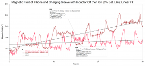
Magnetic Field of iPhone and Charging Sleve with Inductor On (0 and 100 perc. bat. life) linear fit

Notice the linear fit to the collection of points representing the iPhone charging on the pad (the darker red) and see how they have a positive correlation. (click on the graph to view details)

The following graphs and liner fits will highlight how the communication between the sleeve and the charger effectively charges the phone, i.e. if the phone needs more current a higher or increasing field can bee observed, it the phones needs less current (if it has more battery life) then a less and/or decreasing field can be observed.
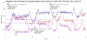
There seems to be a correlation between battery life and magnetic field produced. (click to view details)

There seems to be a correlation between battery life and magnetic field produced. (click on the graph to view details)

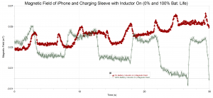
And here again, as the battery life of the phone reaches 100% there is a significant change in the magnitude of the field when it’s charging to when it’s not charging.
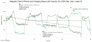
And here an opposite yet expected situation to that of the battery life being at 0% (click on the graph to view details)

And here an opposite yet expected situation to that of the battery life being at 0%. (click on the graph to view details)

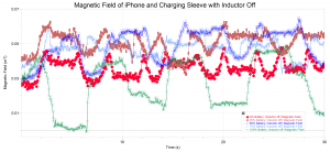
There is an important thing to note in the graph above, the sharp changes in the collection of points representing the not charging state at 100% batter life. In comparison to the other non charging states at different battery life, this one is more drastic (see the graph below). An important detail in science is to recreate an experiment including it’s different trials as similar to all the other trials or experiments. Here I think we have a case of not placing the iPhone in the exact same position as before. As I mentioned earlier we discovered many small magnets dispersed throughout the phone, and during this run we were not being as careful and picked up the magnetic field of one of those magnetic components. Though it does not skew the results significantly, it is important to note.
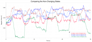
Comparing the non-charging states at different battery life levels. (click on the graph to view details)

Comparing the non-charging states at different battery life levels. (click on the graph to view details)

Implication of Results

These results mean that indeed the method of induction is a valid method for charging devices but with today’s technology the limitations are clear. The limitations being small distances at which these devices can function. If there were to be some way to transmit greater amounts of power very large coils, very high voltages, and very quickly changing, large magnetic fields would need to be implemented. These larger scaled versions of the induction charger would not only destroy the delicate technology in our current devices but the effects that these instruments would have on the human body would be significant (disruption of electrical powered implants, high risk of electrocution, etc).

Comparing Predictions to Results

We were looking for changes in the magnetic field produced by the charger. We expected that if the battery needed more current then the field would be larger and if it needed less the field would be lesser. Our predictions were correct in that sense, however what we didn’t predict would be how quickly (without a large lagging) the communication between devices happened. The runs are not even a minute long and yet in the 30 seconds of being near the charger, the magnetic field reduces itself for the needed purpose immediately.

The Science at Work

A topic familiar to undergrad physics students, the property of induction is the science this charging device capitalizes on. Electromagnetic induction is a curious and yet obvious result of moving (changing) magnetic fields. Any change in the magnetic environment of a conductor will cause an emf (electromotive force; a force that makes electrons move) to be inducted inside that conductor, in other words, a changing magnetic field can induce current in a wire (read more about induction here). This is due to the fact that electrons have a charge (negative) and are affected by the positive and negative, push and pull of a magnetic field. The way in which a changing magnetic field can be produced is by taking some magnet and literally changing its position in space, however, the way in which the charger creates this alternating field is by running current one way and then running it the opposite direction (alternating the current) this is effective because it can be done rather quickly which also makes needing a very large magnetic field irrelevant (at this scale) it can and does however, increase the field strength when needed by running more current in the primary coil located inside the charger. The coil inside the charger runs an alternating current which then produces a changing magnetic field, this field causes the electrons in the coil inside the charging sleeve to move and create a current. That’s the science behind the charger, which also brings up an interesting idea, that the magnetic field sensor is not measuring just one magnetic field, but many of them and all changing.

What would you differently if you had to do this project again?

The main difference would be to have ordered all the needed materials sooner to have avoided delays in collection.

What would you do next if you had to continue this project for another 6 weeks?

I would have liked to taken apart both devices and left them in their basic forms to both measure more accurately the magnetic fields and also to understand the components that lend themselves to being the necessary technologies to enable the effective transmission of current. And maybe, with that information, even try to imagine a more powerful device.
Group 1: Setup and Data

The Reasoning Behind How Data was Taken

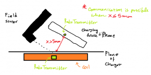
Initially we wanted to measure the magnetic field of the inductive charger by pointing the end of the magnetic field sensor at the center of the charging area, i.e. the center of the induction coil. Unfortunately, due to the distance at which the charging sleeve and inductor communicate (approx 5 mm) it was impossible to get any measurements using this method.

Initial Idea for Experiment Setup

Initial Idea for Experiment Setup (click on image to view details)

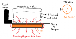
Instead, we placed the sensor parallel to the plane of the charging area and pointed the tip towards the center of the coil. This method, although not as accurate as the initial would have been, did manage to produce relevant data of the magnetic field. Aside from a few issues with not being able to measure the actual magnetic field there was one big problem with this method, but one that could be circumnavigated. As we placed the iPhone onto the charger, with the charger unplugged, we noticed that the sensor detected a change in the magnitude of a magnetic field, it turns out that in the iPhone there are a few magnetic components (in different location of the phone) that produce a field comparable to that of a refrigerator magnet. What we did to get around this issue was to, at a steady rate, place and remove the iPhone from the charger while the charger remained unplugged. And, as it turned out, this was also a much better way to measure the field produced by the charger.

The Setup

The experimental setup was to place the sensor parallel to and on the plane of the charger, with the tip pointed towards the center of the coil. Then, to steadily place and remove the iPhone from the charger, paying close attention to placement of the iPhone (this was due to the fact that the magnetic components of the phone were in different locations which could cause discrepancies in the data).

Final Setup for Experiment

Final Setup for Experiment (click on image to view details)

Initially, this is to be done with the charger unplugged to get a reading of the iPhone’s magnetic field and then with the charger on to see how that field had changed during charging. The trials were done as follows: 0% battery with inductor off, 0% battery with inductor on, 25% battery with inductor off, 25% battery with inductor on, …, 100% battery with inductor off, 100% battery with inductor on.

Data

The data has been organized in the following graphs (note: the units used for measuring the magnetic field are mT or millitesla):

Magnetic Field of iPhone and Charging Sleve with Inductor Off

Magnetic Field of the iPhone and Sleeve (click to view details)

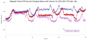
Magnetic Field of iPhone and Charging Sleve with Inductor On (25,50,75 perc. bat. life)

Magnetic Field of iPhone and Charging Sleeve with Inductor On (25,50,75 %. bat. life) (click to view details)

Magnetic Field of iPhone and Charging Sleve with Inductor On (0 and 100 perc. bat. life)

Magnetic Field of iPhone and Charging Sleeve with Inductor On (0% and 100 % bat. life) (click to view details)

Units

As previously mentioned, the unit used in our data collection is the millitesla (One one-thousandths of a tesla) the tesla is the standard unit (SI unit, click here for more info) for measuring magnetic flux density. Flux has to do with the rate at which the magnetic field (in this case) passes through some unit area and density is just how much of the field is passing through the same area, in other words magnetic flux density is the same as saying the magnetic field strength. This unit is named after scientist and inventor Nikola Tesla, not doubt for his contributions in electricity and magnetism. Many of his inventions used magnets to create current, he was also famous for his experiments in wireless power transmission.

Group 1: Project Plan

Motivation:
The innovation of wireless technology has given us convenience in the form of mobility, speed, and efficiency. In addition it has enabled us to go outside our reach to form and keep connections made with people all around the world.

Problem Statement:
There is still a rather inconvenient and significant tether that keeps us from moving with the speed and flexibility that we are capable of, the need for electrical power to be transmitted through wire. The solution: Wireless Power Transmission (WPT).

Approach:
There are a handful of products, known as power mats, on the market that offer WPT for the use of charging cell phones and iPods. The purpose of our investigation is to collect data and analyze the commercial products and with that information build a WPT device of our own. Moreover, we wish to consider the limits, benefits, and further applications of such technology.

Results:
Our device will work by inducing a current with a changing magnetic field. By running current through a primary wire, a magnetic field is created, a secondary receiver coil will experience a change of magnetic flux and thus cause current to run through that coil.

Equipment:

  • Watts Up Pro to measure the needed power to run the power mat as well as to measure the power that is transmitted to the receiver coil in the external device.
  • Magnetic Field Sensor to measure the magnetic field around the coils.
  • Temperature Sensor to measure how the primary and secondary coils heat over time and with different power settings.

Roles:
Juan and Elijah will split up the work on collecting and analyzing data as well as the building of the device evenly. Juan will take care of most of the posts on this website.

Activity Plan:
9/23 – Use Watts Up Pro to measure electrical power and the magnetic field sensor for the magnetic fields present
9/24 – Analyze the data from the measurements
9/25 – Read research papers from Scopus covering WPT
9/26 & 27 – Prepare a plan for building the device and order needed materials
10/2 – Post data onto moodle
9/30-10/4 – Build the WPT device
10/5-8 – Collect data on our device
10/9 – Post data and project results onto moodle

Group 1: Wireless Power Transmission Abstract

Nikola Tesla, the father of alternating current envisioned a world without wires. It was rumored that he devised and successfully tested a contraption that transmitted electrical power through space to light a bulb from a considerable distance! We will investigate commercial wireless chargers used to charge cell phones and iPods to determine the amount of power needed to operate as advertised. With information gathered through the investigation, we will attempt to build a wireless power transmitter, use it to light an LED from a distance, and then explain the physical properties at work and consider the limits of such technology.