Presented below are the analyzed projectile velocities of several test firing runs of our group’s rail accelerator. The data contains limited data points due to the low fps camera’s inability to accurately capture portions of our projectile’s movement. Another factor limiting both the number of data points and the velocity of the projectile is the tendency of the projectile to vaporize and then ionize into plasma upon the current being connected through it. The electric current transforms the projectile which fades away into nothing as it travels through space.
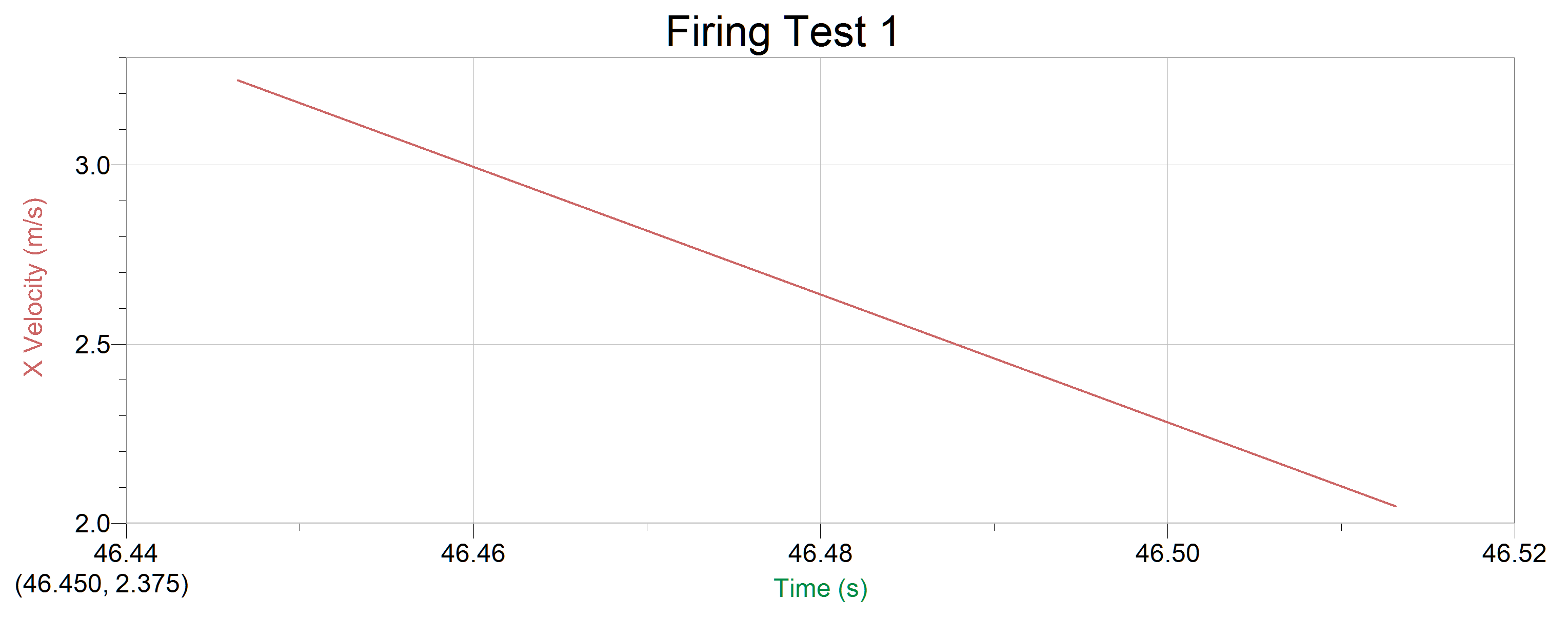
Figure 1: Graphed data from our first firing test (click to enlarge)
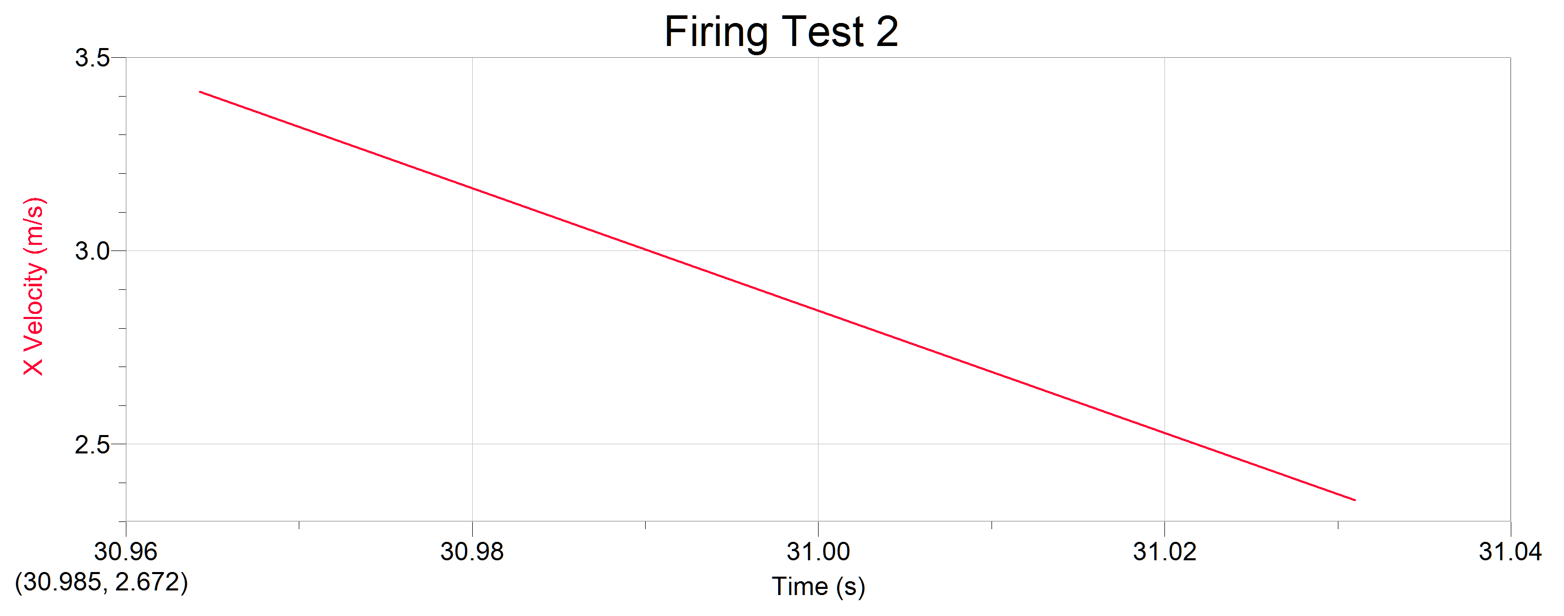
Figure 2: Graphed data from our second firing test (click to enlarge)
These results clearly show the deceleration of our projectile as it fades away and ceases to travel. The initial velocity in the graph represents the velocity as the projectile leaves the rails, no acceleration can be picked up by the camera before then, as the fps is too low to identify the nearly instantaneous acceleration.
The results match our expectations for the projectile’s behavior in that we initially recognized the potential for the projectiles to become plasma. The velocity exhibited seems reasonable given the size of our rail accelerator and projectiles, as well as the relatively low voltage stored in our capacitor bank.
Due to the variable educational backgrounds of our group members, everyone learned something a little different. As an overview we all learned something about the physics involved in the function of a rail accelerator. Specifically we learned through hands-on experimentation about the use of electricity to generate Lorentz force to propel a projectile. A lot of our learning went a little beyond the direct science of the project though, as we all learned something about actually constructing a scientific apparatus for testing.
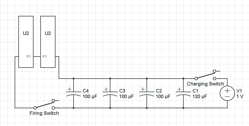
Figure 3: Circuit Diagram for our Rail Accelerator (U2 represents a rail) ((Battery Voltage 1.5V not 1))
If we had to do this project again we would be more attentive to the original construction of our rails and circuit. Small problems in our construction caused major annoyances later in the project. Having constructed a rail accelerator previously would also be largely beneficial. If we were to continue the project, or maybe even in other trials there are several additions we would consider. Testing with different projectiles is the easiest to attempt, if we had suitable materials we might have been able to avoid the problem with the disintegration of our projectiles. If we continued the project it would be interesting to investigate the effects of adding additional capacitors to the charging circuit. Comparing the two charging circuits would clearly show the role the capacitor bank plays in the speed of the projectile fired from the rail accelerator. Another option would be to look into obtaining and using higher quality materials to avoid component failure which adversely affected the entire project.
The initial phase of the our project was to construct a rail accelerator which would be the object of our tests and analysis. This construction involved building separately the two major components of the accelerator, the charging circuit to power the device, and the rails themselves to run the charge through.
Rail Design
The rail design is relatively simple, two thin pieces of aluminum are placed side by side with a gap of about 1/16″ between them. These aluminum bars are sandwiched between two sheets of lucite (clear hard plastic) and via holes driven through all four objects, held together by steel bolts. Our original design had us attaching our leads to these bolts to run current through the rails, but was later changed for reasons that will be discussed when we discuss the challenges presented by testing phases of this project.
Charging Circuit
The charging circuit was slightly more complicated to construct on our end. The basis for the circuit is the circuit board from a disposable camera. using the battery and charging switch from the camera we soldered additional capacitors in parallel in the circuit and added a switch on one side of these capacitors. Using the flash charging switch (or button depending on the camera) to charge our capacitor bank lets us build up charge before releasing it from the capacitors via the switch, completing the circuit with our accelerator wired between the positive and negative of the capacitors.
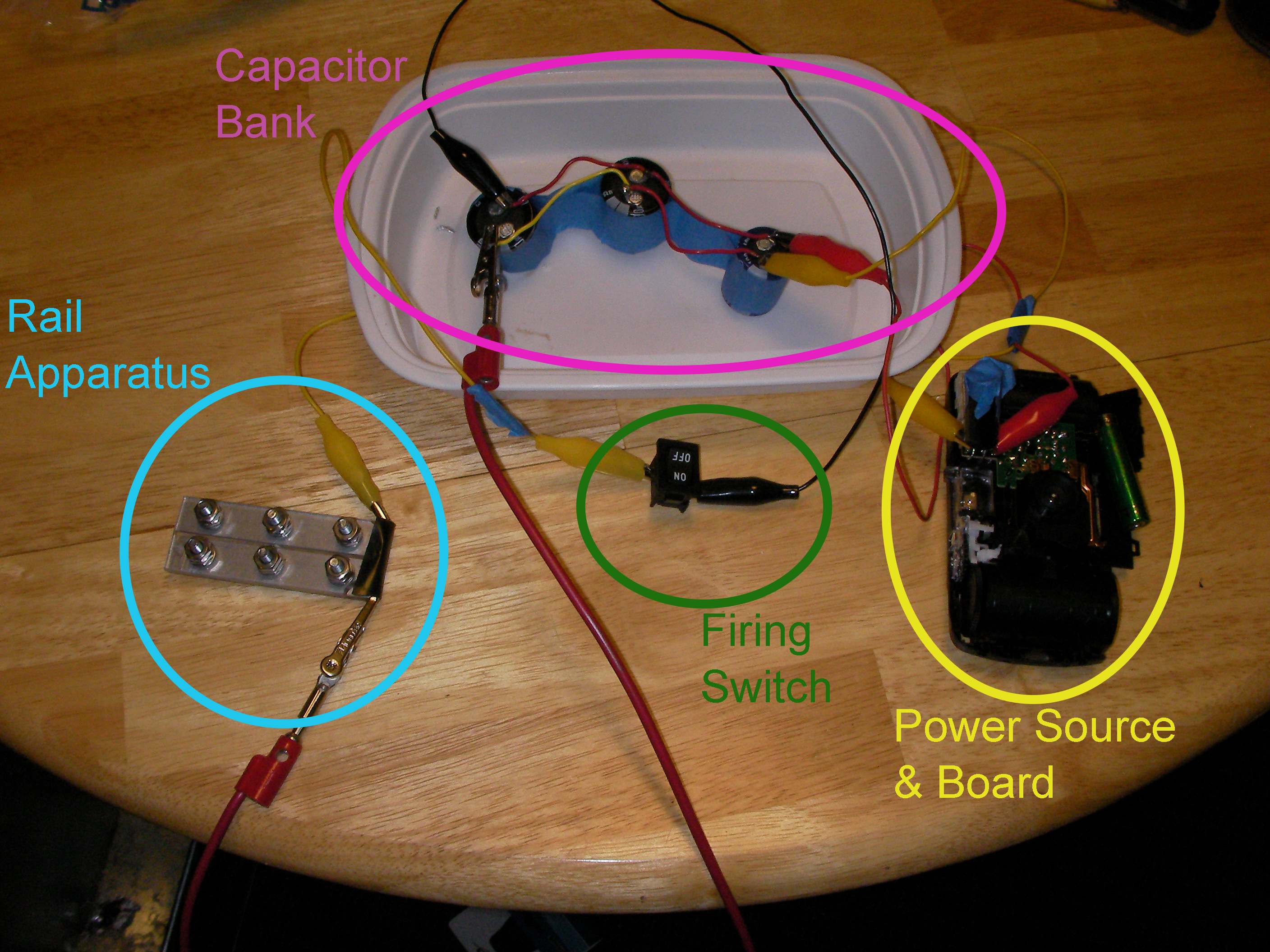
Figure 1. The layout of our rail accelerator as connected (Power source partially removed in this picture)
Experiments and Test:
The initial testing phase of our project focused on testing the parts of the rail accelerator before finally putting the charging circuit to the rail and attempt to fire it. With the rails the only testing that could really be done was an overview examination and the first firing test, with our circuit we had a little more time to test. So in essence our tests are as follows.
Capacitor Bank Testing
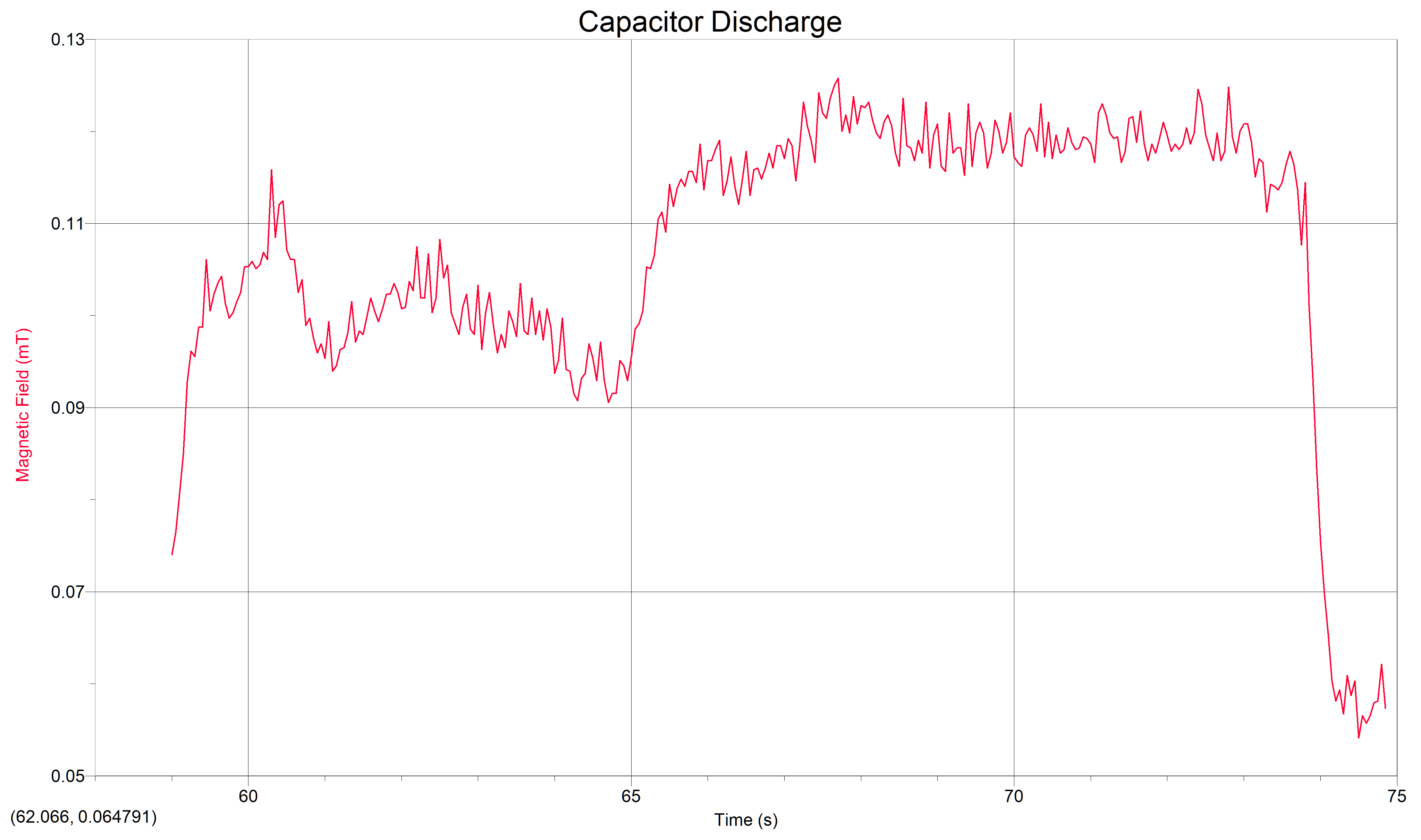
First we tested the capacitor bank to see that it could charge from our power supply and be safely discharged. After managing to properly construct our power supply and setup the charging switch from the camera this was no problem. Our capacitors easily charged and functioned safely even soldered together as a capacitor bank. The second phase of testing for our capacitor bank itself is a test of the magnetic field produced by the electricity in the capacitors, and the change in this field when the capacitors are discharged. The interesting results of these experiments are below.
Figure 2: A graph of the magnetic field around our capacitor bank at the point just before and at discharge. Noticeable drop can be seen.
Figure 3: The values for the Magnetic data represented in Figure 2
Rail Testing:
Testing the rail accelerator itself has been the most problematic phase of our project. First because finding a space to both work with capacitors safely, and potentially fire a small projectile at the same time is not exactly easy on a small college campus. Our original plan was to use the archery field, but the snow (feet of it) seemed to make that seem like less of a good idea, especially because water falling from the sky and electricity don’t really play nicely together.
Phase 1 Rail Testing: So when the time came for initial testing of our rails we found ourselves outside near the archery field later than it was easy to take video results but prepared to test fire anyway. This first trial was a failure. The rails themselves weren’t completing the circuit they way they were intended, and we initially couldn’t figure out why. When we did figure it out the problem was in the construction of the holes for the screws in the rails. Having had the construction done by Carl an assistant to the physics department with access to a drill press, we hadn’t checked that the screws actually made contact with the rails themselves. Since the screws only made contact with plastic, attaching the leads to them wasn’t going to put a current through the rails and allows us to generate our lorentz force by closing the circuit. Because the rest of the rails were covered we had to deconstruct the rail apparatus and clip back some of the lucite so that the clips could be attached directly to the rails.
Phase 2: Our second test and the final test to this point had us once again by the archery field, this time during the day and with a camera ready to test our full system. These tests were a success, and our circuit can be completed and the rail accelerator fired. Videos of small firing can be seen below. Complications still exist at this point however. Firstly, because we are using small pieces of aluminum for our project, the heat from the electricity has a tendency to turn them into plasma, little more than melting aluminum sparks shooting from our rail accelerator. This limits the maximum projectile range, and occasionally simply fuses the aluminum to the rails themselves with the heat. While we do have a few successful tests firing partially plasmified aluminum, the next step before final data analysis and reporting will be to attempt to fire a more substantial material and compare the results.
Figure 4: Our first firing of the Rail Accelerator skip all the time it took to charge
Figure 5: Another shot of the accelerator firing. Watch for the spark shooting from the rails, that’s what’s left of the projectile by the time it leaves the rails
Roles: All members will be equally involved in testing and measuring phases of the project. Each member of the group will take part in operating and observing the function of the rail accelerator and recording the results of test firings. Jarrett Holtz will be in charge of construction of the rail accelerator, and Austin Rau will oversee physics principles in the construction of the device.
Equipment and Supplies:
Aluminum weld bars
Sheet of lucite
Nuts and bolts
4 disposable cameras (for the capacitors and circuit board)
Heavy wire
Two switches (not necessary but ideal)
Aluminum foil
Graphite
Steel shot
Recording camera
EMF meter
Science/Technology Involved: From a scientific perspective the rail accelerator is a utilization of electromagnetism. Current through a pair of parallel metal rails creates a circuit that is closed by a conductive material placed between the charged rails. Completing the circuit creates a Lorentz force that pushed on both the fixed rails and the object between the rails, essentially turning any conductive magnetic material between the rails into a projectile. Technologically the rail accelerator utilizes circuit boards and a carefully constructed circuit to charge a pulse of electricity to be used to generate the Lorentz force necessary to propel the projectile. That along with the design of the rails completes a projectile launching technology using only electromagnetism as sources of propulsion.
Construct the charging circuit and connections to the rails
Test the rail accelerator’s operation initially for repeatable successful firing (firing tests will be done on the archery field)
Test with different sizes and different materials of objects (aluminum foil, graphite, small steel shot)
Measure the electromagnetic field generated by the rail accelerator and charging circuit
Record video of projectile launches for different projectiles
Determine speed using video analysis software for projectile types
Analyze data
We will be meeting with Carl Bertsche on Monday 02/10/14 to get holes drilled in the rails and lucite with which to build the actual rail mechanism. After we have the actual rails finished it will be a matter of completing the charging circuit. All of which will be completed within the week. After that I foresee that with no complications our data will be taken the following weekend, or the beginning of the next week.
Safety Plan: In the construction process and after firing all capacitors will be completely discharged and all power sources removed to account for electrical safety. There should be no power to the device when not in operation. For firing purposes the firing end of the accelerator will be given a clear space, and people will keep clear of the front of the device. In general precaution will be taken with the device during construction and firing, respecting the potential danger of both electricity and projectiles.
Outcomes/Data Expectations: We expect to see a static electromagnetic force generated for each projectile with the speeds varying based on the mass of the projectile and the material. Based on the heat generated by the large amounts of electricity through the projectiles it is possible that we will see some damage (destruction) of the projectiles such as the aluminum foil. I suspect that the lighter materials will move at faster rates, but we don’t expect exceptional speeds from a rail accelerator of a size this small utilizing such a small power bank.
A rail accelerator is a device that uses electromagnetic force and metal rails to propel objects at high speeds. For this project our goal is to build a small functional rail accelerator based on publicly available instructions, and then to take data on experiments run with our final product.
Once the rail accelerator is finished we will take data on the electromagnetic forces generated around the rails to propel our projectiles. As well as the velocities of the projectiles themselves as they leave the rails, possibly varying the type of projectile.