Experiment Setup and Background:
Rail Accelerator Construction
The initial phase of the our project was to construct a rail accelerator which would be the object of our tests and analysis. This construction involved building separately the two major components of the accelerator, the charging circuit to power the device, and the rails themselves to run the charge through.
Rail Design
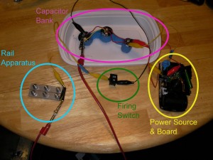
The rail design is relatively simple, two thin pieces of aluminum are placed side by side with a gap of about 1/16″ between them. These aluminum bars are sandwiched between two sheets of lucite (clear hard plastic) and via holes driven through all four objects, held together by steel bolts. Our original design had us attaching our leads to these bolts to run current through the rails, but was later changed for reasons that will be discussed when we discuss the challenges presented by testing phases of this project.
Charging Circuit
The charging circuit was slightly more complicated to construct on our end. The basis for the circuit is the circuit board from a disposable camera. using the battery and charging switch from the camera we soldered additional capacitors in parallel in the circuit and added a switch on one side of these capacitors. Using the flash charging switch (or button depending on the camera) to charge our capacitor bank lets us build up charge before releasing it from the capacitors via the switch, completing the circuit with our accelerator wired between the positive and negative of the capacitors.
Figure 1. The layout of our rail accelerator as connected (Power source partially removed in this picture)
Experiments and Test:
The initial testing phase of our project focused on testing the parts of the rail accelerator before finally putting the charging circuit to the rail and attempt to fire it. With the rails the only testing that could really be done was an overview examination and the first firing test, with our circuit we had a little more time to test. So in essence our tests are as follows.
Capacitor Bank Testing
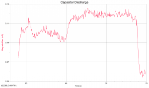
First we tested the capacitor bank to see that it could charge from our power supply and be safely discharged. After managing to properly construct our power supply and setup the charging switch from the camera this was no problem. Our capacitors easily charged and functioned safely even soldered together as a capacitor bank. The second phase of testing for our capacitor bank itself is a test of the magnetic field produced by the electricity in the capacitors, and the change in this field when the capacitors are discharged. The interesting results of these experiments are below.
Figure 2: A graph of the magnetic field around our capacitor bank at the point just before and at discharge. Noticeable drop can be seen.
| Time (S) | Magnetic Field (mT) |
|---|---|
| 71.95 72 72.05 72.1 72.15 72.2 72.25 72.3 72.35 72.4 72.45 72.5 72.55 72.6 72.65 72.7 72.75 72.8 72.85 72.9 72.95 73 73.05 73.1 73.15 73.2 73.25 73.3 73.35 73.4 73.45 73.5 73.55 73.6 73.65 73.7 73.75 73.8 73.85 73.9 73.95 74 74.05 74.1 74.15 74.2 74.25 74.3 74.35 74.4 74.45 74.5 74.55 74.6 74.65 74.7 74.75 74.8 74.85 |
0.121015622295 0.119624020764 0.11782958721 0.118623044224 0.118024899706 0.118623044224 0.120417477777 0.118623044224 0.119819333259 0.124592282371 0.123005368344 0.119624020764 0.118220212201 0.11682861067 0.119819333259 0.11682861067 0.11782958721 0.124787594867 0.119416501237 0.117634274714 0.120014645755 0.120808102768 0.120808102768 0.118818356719 0.115046384147 0.117036130197 0.116633298174 0.111262204544 0.114240720103 0.114045407607 0.113654782616 0.114448239629 0.116437985679 0.11782958721 0.116437985679 0.113654782616 0.107673337437 0.114448239629 0.101105954771 0.0931469705743 0.0834057598545 0.0754345686264 0.0698681625008 0.06548583838 0.0603100572457 0.0581249987008 0.0593212877366 0.0567333971694 0.0609082017636 0.0587231432187 0.0603100572457 0.0541455066023 0.0565380846738 0.0557324206293 0.0565380846738 0.0579296862052 0.0581249987008 0.0621044907994 0.0573315416873 |
Figure 3: The values for the Magnetic data represented in Figure 2
Rail Testing:
Testing the rail accelerator itself has been the most problematic phase of our project. First because finding a space to both work with capacitors safely, and potentially fire a small projectile at the same time is not exactly easy on a small college campus. Our original plan was to use the archery field, but the snow (feet of it) seemed to make that seem like less of a good idea, especially because water falling from the sky and electricity don’t really play nicely together.
Phase 1 Rail Testing: So when the time came for initial testing of our rails we found ourselves outside near the archery field later than it was easy to take video results but prepared to test fire anyway. This first trial was a failure. The rails themselves weren’t completing the circuit they way they were intended, and we initially couldn’t figure out why. When we did figure it out the problem was in the construction of the holes for the screws in the rails. Having had the construction done by Carl an assistant to the physics department with access to a drill press, we hadn’t checked that the screws actually made contact with the rails themselves. Since the screws only made contact with plastic, attaching the leads to them wasn’t going to put a current through the rails and allows us to generate our lorentz force by closing the circuit. Because the rest of the rails were covered we had to deconstruct the rail apparatus and clip back some of the lucite so that the clips could be attached directly to the rails.
Phase 2: Our second test and the final test to this point had us once again by the archery field, this time during the day and with a camera ready to test our full system. These tests were a success, and our circuit can be completed and the rail accelerator fired. Videos of small firing can be seen below. Complications still exist at this point however. Firstly, because we are using small pieces of aluminum for our project, the heat from the electricity has a tendency to turn them into plasma, little more than melting aluminum sparks shooting from our rail accelerator. This limits the maximum projectile range, and occasionally simply fuses the aluminum to the rails themselves with the heat. While we do have a few successful tests firing partially plasmified aluminum, the next step before final data analysis and reporting will be to attempt to fire a more substantial material and compare the results.
Figure 4: Our first firing of the Rail Accelerator skip all the time it took to charge
Figure 5: Another shot of the accelerator firing. Watch for the spark shooting from the rails, that’s what’s left of the projectile by the time it leaves the rails


I applaud you for building your own device and taking measurements on that device. For your conclusion, I would be very interested in seeing a schematic of your setup. Also, where did you find the building instructions?