Author Archives: mohowe

Relativistic E&M: Final Conclusions

While I did succeed in creating a model that allowed the user to view the field at different speeds, it only managed to show the direction and relative magnitude compared to the rest of the current fields. If I were to continue with this project, I would attempt to improve it in several ways.

-First, I would try to find a way to make Mathematica account for the absolute magnitude of the fields so that the uniform fields would appear to change as the speed was varied. This might be accomplished by using equipotential surfaces rather than vector fields.

-Second, I would write code such that the user could simply input (or maybe copy and paste) a particular E-field equation for a rest frame, and the program would interpret the equation and produce the vector plots with sliders as shown in my model.

-Third, I would model more discrete situations rather than infinite distributions of charge or current so that the changes in field would be more visible.

-Fourth, I might consider a different type of plot, since Mathematica seems to deal with this kind of plot poorly. For instance, a static plot of E versus v and B versus v at a single point in space might better show the changing relative magnitudes of the fields.

That being said, this project was successful in several regards. It emphasizes the interplay of electric and magnetic behaviors when considered in moving reference frames, and at least in the case of the point charge, it allows for an examination of the changing shape of the fields at different speeds. It also sets up the framework for being able to model more complex systems by providing a proof-of-concept using simpler cases. Therefore, this project successfully modeled the fundamentals of relativistic electromagnetism, and provides a good foundation for a more in-depth exploration.

Share

Final Results: Modeling Relativistic E&M

The next step of my project involved applying the modeling and manipulation code to different scenarios. In this case, I chose two scenarios that started as purely electric and developed magnetic components when considered in moving reference frames. The first was a continuous case- an infinite parallel-plate capacitor, and the second was a discrete case- a single point charge.

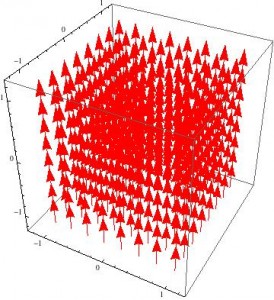
As has been well established, the field between two capacitor plates of charge density +/-σ is E=σ/2ε0. It is unsurprising then, that the E-field of a capacitor looks like this:

capacitor rest E

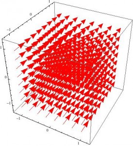
It is equally unsurprising that since there is no moving charge, there is no B-field. Then, when the system is considered in a reference frame moving at speed v relative to the capacitor and the transformation equations are applied, the following fields emerge for E…

capacitor rest E


and B…capacitor moving B

These look pretty dull, but are a few things to note about these figures. The first is that Mathematica is not able to show absolute magnitude of the vector fields: just the relative magnitude. That is, the arrows are the correct size relative to the other arrows in the box, but they are not necessarily to scale when compared to other fields. This is why the plots appear unchanged when v changes: the values of the vectors are all changing, but all at the same rate, so the pictures do not change.

The second notable feature is that (without accounting for the actual magnitudes of the fields), it is possible to see that even though the E- and B-fields both change, the direction of the net force does not. For a positive test charge at rest in the reference frame moving in the x-direction, it would experience only an electrostatic force in the z-direction in the rest case. For the moving case though, it would experience an E-field still in the z-direction and a B-field in the y-direction, both of which would result in a net force that is still in the z-direction.

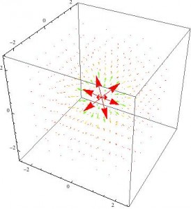
Despite the simplicity of a point charge, this third case is actually the most interesting to look at because it is not infinite, but discrete. Thanks to every intro E&M course we’ve ever taken, we know that the E-field created by a test charge is E=q/r24πε0. The following vector plot or something similar probably appears in every intro textbook currently on the market.

pt charge rest E

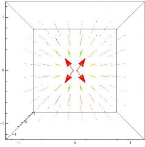
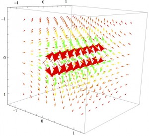
Pretty boring, right? Completely spherically symmetric and falls off with r2 as expected. Now for the interesting ones: the fields in a moving reference frame. The E-field actually starts losing gaining so much of a y- and z-component that it appears to flatten out in the x-direction. The following figure is for v=0.75c

pt charge moving E

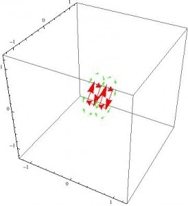
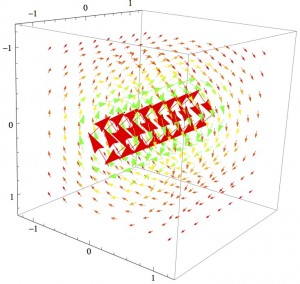
The B-field does something equally strange: it becomes somewhat cylindrical. However, in my code, this only appears at very high v (greater than 0.96c).

pt charge moving B

I get the feeling that if I could make mathematica show more detail, the field would not be in a perfect cylinder though. Since two rings of vectors appear on either side of the origin, it may be that the actual field has two lobes of some sort that are symmetric about the x-axis.

The last thing to note about this model is that when v=c, the simulation returns an error because it has to divide by zero when calculating gamma. Furthermore, the expression for gamma returns imaginary numbers for v>c, so this model is not useful for considering hypothetically how a system might behave if anything were able to move faster than the speed of light.

The mathematica worksheet associated with this can be found here.

Share

Relativistic E&M: Preliminary Results

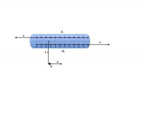
It is fairly easy to see that the electric and magnetic fields of various systems change drastically when considered in different reference frames. For example, consider a wire with a line of positive charges moving to the right at speed v, and an equal line of charges moving to the left at speed v.

current wire B only

This system has a net charge of zero, so there should be no electric field. However, the sum of the charges does cause a total current I = 2λv to the right, which gives a magnetic field of B = μ0λv/πs in the ϕ direction (as dictated by the right-hand rule), for any distance s from the center of the wire.

current wire B0 vector

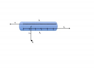
Now, consider the same situation, but in the reference frame where q is at rest. Suddenly, the positive linear charge is much smaller than the negative one, leaving a net negative charge on the wire, which will produce an electric field. Simply by changing the reference frame, the situation switched from a purely magnetic phenomenon to a combination of electric and magnetic.

current wire EB

However, rather than trying to analyze the magnitude of the new charge and current values to find E and B, it is possible to simply use the following transformation equations to find out what the new E and B fields are.

$E’_x$ = $E_x$
$E’_y$ = $\gamma$ ($E_y$ – $vB_z$)
$E’_z$ = $\gamma$ ($E_z$ – $vB_y$)
$B’_x$ = $B_x$
$B’_y$ = $\gamma$ ($B_y$ + $\frac{v}{c^2}$ $E_z$)
$B’_z$ = $\gamma$ ($B_z$ – $\frac{v}{c^2}$ $E_y$)

Where $\gamma$ = $\frac{1}{\sqrt{1-{\frac{v^2}{c^2}}}}}$ (From Griffiths Introduction to Electrodynamics, 3rd Ed. p531). The only hiccup is that the original setup is in cylindrical coordinates, while the transformation equations are in Cartesian. However, Mathematica can do this automatically, so I’m going to leave it in these terms.

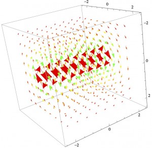
B-field:current wire B1 vector E-field:current wire E1 vector

The Mathematica file contains 3D vector plots of the E and B fields for the rest frame and a frame moving at v=0.25c, but so far, I haven’t figured out how to make it so that the user can vary the speed of the reference frame. Hopefully, I will figure that out soon. The key thing to note is that the model shows the interplay of E and B fields at relativistic speeds: the scenario starts out completely magnetic and ends up a mix of the two.

Share

Revised Project Plan: Relativistic E&M

So it seems that step 1 of my original plan is more involved than I thought. To satisfactorily derive the E- and B-field transformation equations, it would be necessary to delve into the depths of relativistic mechanics, including the transformation of equations for motion, momentum, and energy, among others. This seems like it is outside the scope of the project: indeed, Griffiths spends about 55 pages before he is able to state the field transformation equations. I thought there would be a point halfway through at which I could pick up and start the derivation, but I was incorrect, so I am going to take the transformation equations as given, and work from there.

That being said, my new timeline will be essentially the same as the old one, just starting at what used to be Step 2 with the application of the transformation equations to one or two situations.

1) 4/14-4/18: Pick one or two simple scenarios and find their E- and B- fields if they were traveling in a moving reference frame. This will be a computational step. The transformation equations are pretty straightforward, so it should take less time. This is just to have a proof of concept, so it is less important that the system has interesting behavior in a moving reference frame.

2) 4/18-4/24: Make 3D or 2D vector field models of these situations in Mathematica. This portion will be focused on figuring out how to make mathematica do what I want. The goal is to come up with an animation or interactive figure that can be used to view the vector fields when the system is moving at different speeds, starting at non-relativistic speeds and working up to the speed of light.

3) 4/24-5/2: Find and model situations that display either representative or unusual behavior when considered in a relativistic reference frame. Once the Mathematica simulation for the first situation has been figured out, the following cases should be easier to take care of. Interesting behavior might include systems that only have an electric field in one reference frame and only a magnetic frame in another. It also may be interesting to consider what happens if a reference frame is moving faster than the speed of light.

4) 5/15/14: Summarize results and write conclusions. This will consist of a final look at the systems considered earlier and suggest possible directions for future exploration.

Share

Project Plan: Relativistic E&M

Sources: In terms of sources, this project is fairly simple. The main source will be Chapter 12 of Griffiths’ Introduction to Electrodynamics, 3rd ed. This will provide a framework for deriving the transformation equations.

Process/Timeline: There are five main steps involved in this project:

1) 4/7-4/14: Derive the transformation equations. This will be a proof-based step, and I need to refresh myself on some of the concepts of mechanical relativity, so it may take some time.

2) 4/14-4/18: Pick one or two simple scenarios and find their E- and B- fields if they were traveling in a moving reference frame. This will be a computational step. The transformation equations are pretty straightforward, so it should take less time. This is just to have a proof of concept, so it is less important that the system has interesting behavior in a moving reference frame.

3) 4/18-4/24: Make 3D or 2D vector field models of these situations in Mathematica. This portion will be focused on figuring out how to make mathematica do what I want. The goal is to come up with an animation or interactive figure that can be used to view the vector fields when the system is moving at different speeds.

4) 4/24-5/2: Find and model situations that display either representative or unusual behavior when considered in a relativistic reference frame. Once the Mathematica simulation for the first situation has been figured out, the following cases should be easier to take care of. Interesting behavior might include systems that only have an electric field in one reference frame and only a magnetic frame in another. It also may be interesting to consider what happens if a reference frame is moving faster than the speed of light.

5) 5/15/14: Summarize results and write conclusions. This will consist of a final look at the systems considered earlier and suggest possible directions for future exploration.

Share

E&M Scenarios Reimagined in Relativistic Reference Frames

While this class has covered the electric and magnetic fields of stationary objects, it has not addressed the concept of objects in motion. In this project, I will first derive the relativistic transformation equations for electric and magnetic fields. Then, I will apply these equations to a number of scenarios that have already arisen in the stationary form, such as a parallel plate capacitor, a bar magnet, a solenoid, and a current-carrying wire. These scenarios will then be assessed at varying speeds.

Share