Staying true (so far) to my tentative project timeline, I acquired images of the C. elegans in various shapes, I have done quite a bit of research on Fourier Transforms and Fraunhofer Diffraction, and so far I have successfully transformed one image into the corresponding diffraction pattern.
IMAGE 1
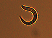 I took this image and used
 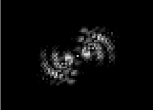 mathematica to sharpen it –> setting it to grayscale and brighten it –> collect dimensional information –> apply a Fourier Transform, yielding (after some similar image manipulation):
This is a great diffraction pattern, but I had issues with the poor resolution and general image quality. To remedy this, I proceeded with images taken with a higher-resolution camera.
(full file for image 1: book 1 )
IMAGE 2
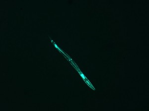
This beautiful image needed some manipulation, similar to image 1: I converted it to grayscale –> brightened it significantly (to make it a more definite shape, and to get rid of the “holes” in the luminescing nematode) –> collected image dimensions and data –> applied the FT. Unfortunately, I ran into a problem.
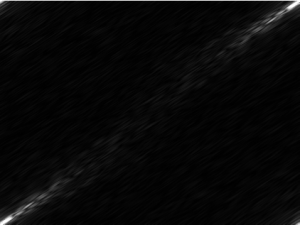
The produced image:
Obviously this is quite different than the first diffraction image.
I had a few hypotheses:
1. The image was saved as a .jpg, but the same image was produced when I tried again with a .png version of the image.
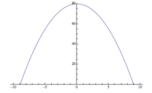
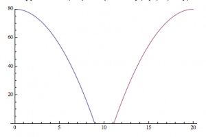
2. The computer is phase- shifting the image so that instead of the origin lying in the center of the product, it is splitting the right side from the left side and lining them up in the wrong order. How can I rearrange and correct the phase shift in the output?
An analogy to the second hypothesis:
—>
It is as if, instead of centering the origin in the center of the produced diffraction pattern, the computer is putting the “origin” in a different place, and splitting the image, similar to the parabola I produced above.
My solution is a little underhanded. I divided the image into four equal rectangles, and manually rearranged them to produce what I knew was the true image: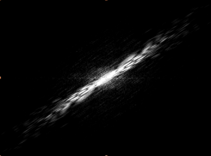
(full file for image 2: book 2a book 2b )
—————-
Reflection:
It is important to keep this process grounded: how is this relevant to Electromagnetism? The answer is that this entire process is only viable because of the laws of electromagnetism. I am analyzing the images by taking their Fourier Transforms. The diffraction pattern is the FT of the function that describes the electric field strength across the aperture of diffraction. In other words, I am applying an operation (the FT) to the image, which is a direct indication of the electric field strength across the aperture (the microscope slide) to mathematically find the diffraction pattern produced by the specific electric field array created by the shape of the worm.
Specifically, the diffraction pattern here is the Fraunhofer Diffraction pattern, or “far-field” diffraction, which occurs when the distances between the screen, aperture, and light source are appropriately far $L>>\frac{b^{2}}{\lambda}$. Diffraction effects are an outcome of the type of light wave.
It is also essential to realize what information is lost in the computation of these diffraction patterns. I am taking a real image, applying a FT to it, squaring the absolute value of the result, and arriving in a complex space. This process loses the phase information of the light, and as a result, it is possible to go from the image to the diffraction pattern, but impossible to find the image from the FT diffraction image.


Nice job. It looks like your script is too large for Google Drive. You may want to break down your file into several smaller files or use vspace.