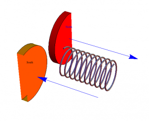
As discussed before, I will be looking at how magnetic fields induce currents in wire coils. The setup I have chosen to focus on has magnets passing over a stationary coil as shown below.
For the purpose of my diagram, we see a north, a south, and another north pass over the coil. Each magnet has a radius of 2cm and 1cm gap between them. This is one of the few things that is not variable in my animation.
The first thing I will concern myself with is producing the equation for the magnetic field. I will start with the following equation:
(1) ![]()
After plugging in the constant for ![]() and scaling it to get millitesla I get the equation:
and scaling it to get millitesla I get the equation:
(2) ![]()
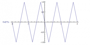
Aha! I have the magnetic field dependent on distance. This is great, but I am more interested in having one dependent on time. Here is where the heavy lifting comes in. I will now assume that all of my other variables are constant, with the exception of time. Time should only effect one thing with the magnetic field, and that is the direction of the field. This changing magnetic field is the exact effect that we need to make induction work. Since the only change is the direction we know that the range of the field is -B to B. This means that we need a function that oscillates linearly from 1 to -1 and then multiply our equation derived for B by this new oscillating function.
The reason I chose a linear function, is because as one magnet moves away an opposite one moves in. I am going to make the assumption that when the north facing and south facing magnets are equidistant from the center of the coil, the magnet field within is zero. What I hope to achieve is a function that will linearly rise and fall from 1 to -1, and what better way to do that than with a triangle function.
The equation for this triangle function is:
(3) ![]()
Where p is the period, and the bottom side brackets ![]() are floor functions.
are floor functions.
As stated earlier the magnets have a radius of 2cm and separation distance of 1cm. Since this is constant we know that the distance between the peaks of the triangle function has to be 10cm (2+1+4+1+2) using the equation ![]() we can say that
we can say that ![]() .
.
Using this new definition of p, (and assuming v is constant) we get the following equation:
(4) ![]()
which in turn leads us directly into our new equation for B:
(5) ![]()
We have successfully found B as a function of t!
Now we have the magnetic field some distance from the magnet. The next step is to find the flux. Since in my diagram the magnet is larger than the coil (and at most the same size) I will only worry about the coil’s area. I also have no pitch on the magnets or wire, so angle is irrelevant and will be ignored from here on. Using the following equation:
(6) ![]()
we find:
(7) ![]()
Where ![]() is the diameter of the wire and N is the number of turns.
is the diameter of the wire and N is the number of turns.
Since one of the main goals is to find the emf, we need to find ![]() with respect to t. Luckily, we did most of the work already when we derived B(t). The new equation reads:
with respect to t. Luckily, we did most of the work already when we derived B(t). The new equation reads:
(8) ![]()
For simplicity I will quickly denote ![]()
We can now move along to the emf!
(9) ![]()
Plugging in our absurdly long equation for the flux, we get:
(10) 
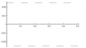
How would you take a derivative of this triangle function with respect to t? Well, you can’t. At least, I can’t, but what I can do is find an adequate approximation. I know that the positive slope is ![]() and the negative slope is
and the negative slope is ![]() . From here I can ascertain the derivative simply by finding a function that flips back and forth between those two values every
. From here I can ascertain the derivative simply by finding a function that flips back and forth between those two values every ![]() , which should look like a square function.
, which should look like a square function.
The equation for which is:
(11) ![]()
Where the sgn function simply takes all positive values and makes them 1 and all negative values and makes them -1. This gives us an emf of:
(12) ![]()
and an induced current of
(13) ![]()
HUZZAH!!


