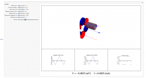
Mistakes were made throughout this process. Some were as simple as a dropped variable and others were intensely more complicated. In the end I was still able to produce what I set out to do: An interactive animation that allows you to see how a single coil in a stator of magnetic induction based wind turbine creates current.
Much of the work I did was simply writing the code to get the interactive animation to function properly. Below is a screenshot, but the important code is linked to at the end of this post.
Just to recap some of the derivation I did in earlier posts, I will present a short breakdown here. I started with the basic equation for B, but in order to have the magnetic field change over time based on my magnet array, I had to use a triangle wave. In my previous post I inserted values for the period, but in my Mathematica code, I made it dependent on the velocity so that all the graphs would match up.
Triangle Wave Function:
(1) ![]()
Magnetic Field Equation
(2) ![]()
Once I had my B(t) I quickly found the flux, but to get to the voltage I had to find the derivative of my triangle wave based B(t) function. I made a square wave approximation to solve for the derivative. In my last post I again plugged in constants in order to show the look of the graph, but in my code I made it dependent on all of the variables.
(3) ![]()
Using this square wave approximation I was able to find the voltage in the coil. Once I had a formula for the voltage, the induced current was simple to find.
At this point I noticed a grave mistake with my approach to this problem. By approximating the magnetic field with a triangle wave, I made it so the voltage simply flipped back and forth from negative to positive with no gradation. In hindsight it would have been better to use a version of a sin wave as an approximation. That would present its own issues, as the magnetic field would have a fairly linear change. With more time I would have attempted to find a better approximation for the magnetic field that was easier to use.
It should also be noted that my last post had a few typos in it that could be very confusing. I wrote the equation:
(4) ![]()
but it should read:
(5) ![]()
The mu was confused for most of the post, but I was able to correct the issues I had with it for all of the formulas in this post and the code.
Code: https://vspace.vassar.edu/thvandermeer/Trying%20to%20get%20graphs%20in%20it.nb


I like the coherence of your project. Being critical of your own work is an important skill that you have achieved. I would be interested in an attempt in realistically modeling/approximating the flux as a function of time. This would not have been easy since you chose 2 circular areas. I am wondering what shapes are the most efficient ones?
Theo good job with your animations I especially had troubles trying to make mathematica do what I wanted. I think a diagram of how an actual turbine works then zeroing on how a single magnet and coil works (what you did) would make the readers visualize exactly what you are talking about. As you said in class using Fourier transformations equations to model would work better and I would have liked to see the changes it would have made in your magnetic field and flux graphs. It would have been especially helpful to show the magnetic field lines and the resulting induced current in your animations (if that is possible) and if the current induced was AC or DC. I think a real world example of how much wind needs to blow to let’s say supply power for a fridge/TV could give us some reasoning as to why they are not so widespread.
Having done a very similar project, I can really appreciate a lot of the work that you put into this. The derivation of your equation for the magnetic field was very clear and concise, especially given the complexity of the system that you were modeling. This clarity and careful explanation was a theme throughout your blog: everything was laid out in detail, no steps being excluded regardless of what you were explaining. This is a very important part of scientific writing, as I am sure you are aware, and you accomplished it admirably.
I also think that you did a good job in accomplishing your initial goals. That is to say, the scope of and objectives for your project did not exceed your capabilities.
One thing that I would have liked to see more of would have been tying your research here to the construction and operation of your own induction generator. The fact that you were building the system that you were modeling (or at least a very similar system) presents a unique opportunity for testing your model, and maybe inspiring revision. This is especially true given that you were examining efficiencies, a largely experimental phenomenon.
Overall, there were no large flaws in your work. The opportunity that I mentioned above falls more into the realm of things that might have added to your project than things that detracted from it. One suggestion I would have made is to use a Fourier Transform to approximate your triangle wave, but that is the only thing that stood out. You did a great job displaying all of your data and derivations in a way that was clear and easy to understand (especially the final animation of your generator), and you accomplished everything that you set out to accomplish.