Week 3

Exciting things happened this week in the VAOL lab.  For the first time this semester we were able to collect data on the worms.

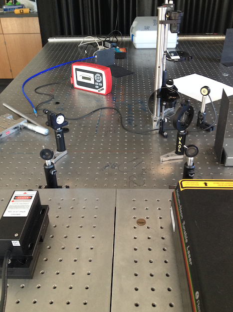
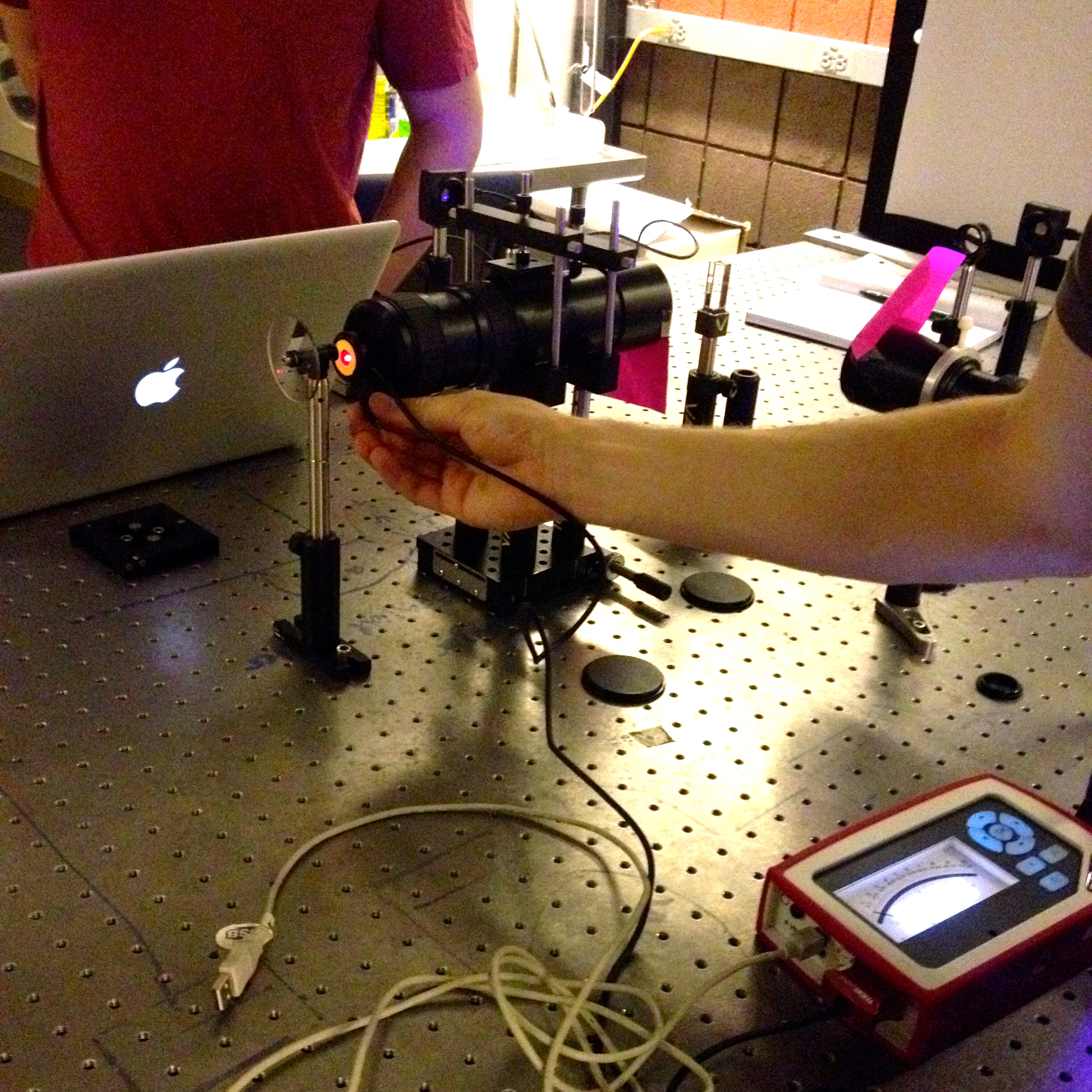
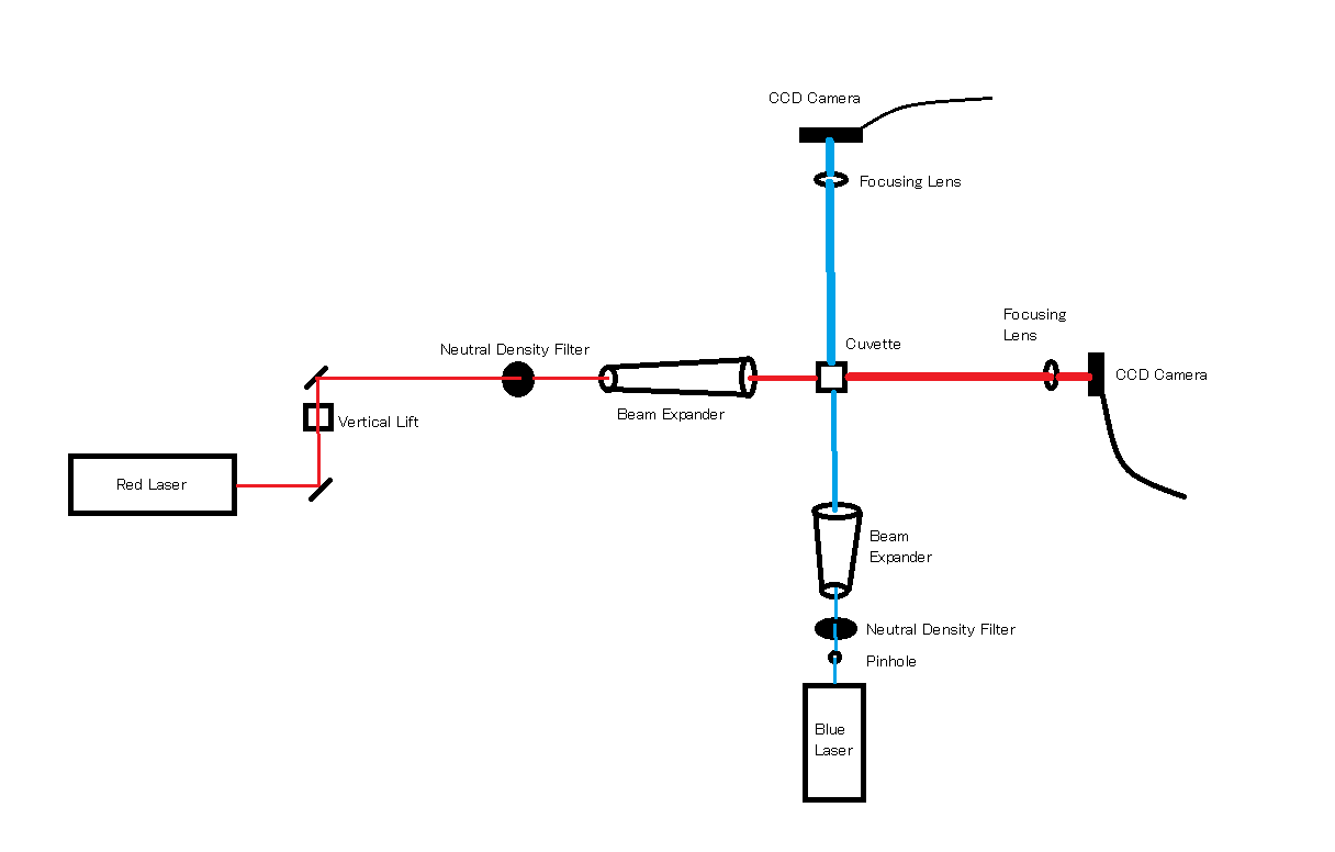
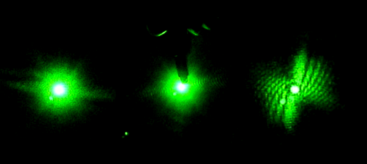
In the beginning of the week we spent time practicing transferring the worms from the cup they are grown in, into a cuvette filled with distilled water.  This is more challenging than one would expect because the worms are microscopic and the process must be down under a microscope, using a tiny pick to lift the worms up and transfer them to the cuvette.  We also practiced finding the worm once it was in the cuvette and getting the laser to pass through them to create a diffraction pattern.  Once the worm is found in the cuvette with the naked eye it is pretty easy to keep the laser on it as it swims around.

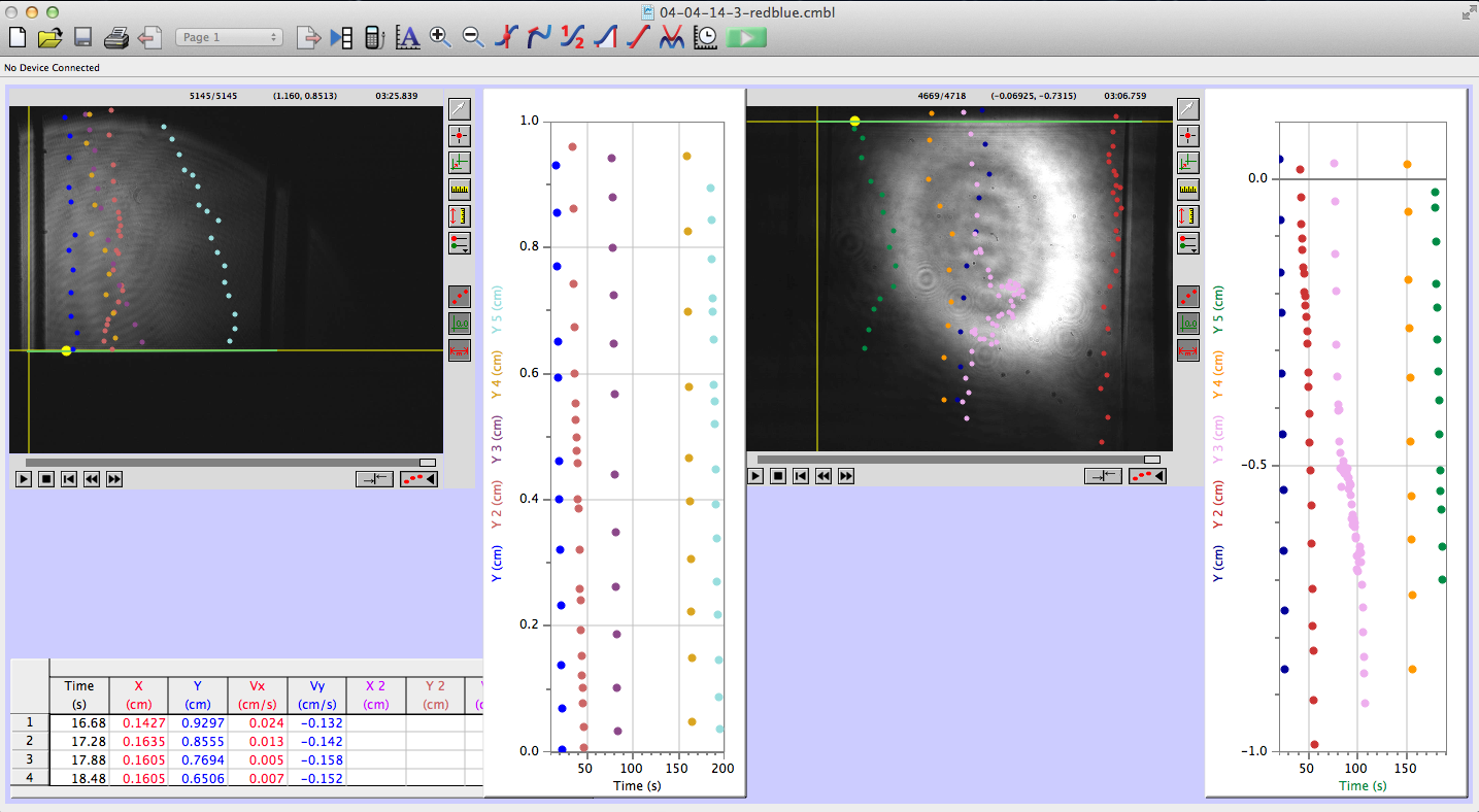
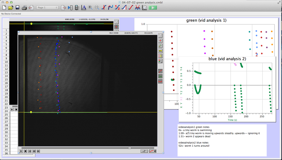
Later in the week, we actually collected data using the pico scope software on the computer.  The pico scope evaluates the change in diffraction pattern observed by the photo diode as the laser passes through the worms.  It then shows the results in voltage.  We ran trials on four worms total, getting data for each one using only the red laser.  The plan is to continue running data on more worms with both the blue and red lasers, after which we will combine all the data for analysis.

Things are finally starting to come together in the lab after what seemed like a lot of grunt work putting the lab together after the move.

Week 2

This week saw a lot of progress for the lab.

We were able to finish the table set up.  It is pictured below. To the left you can see the blue laser. This laser is sent through a pin hole to a mirror that reflects the beam to the right at a beam splitter.  The beam splitter sends part of the beam towards the slide holder, and another part to the black shield at the right.

On the right is the Helium Neon laser (red laser).  The red laser is aligned to also go through the beam splitter and to the slide holder.

This set up allows us to easily switch between the lasers without having to adjust the set up.  A slide will be placed on the slide holder, and as the beam passes through the object on the slide, a diffraction pattern will then be read by a photo diode detector.

This week I also learned how to grow and maintain the C. elegans population we will be using for analysis.  This process involves using a microscope to transfer a few mature C. elegans to a new tray with food from a pre-existing non-mutated population.  These mature worms will then reproduce and give rise to a new population.  The C. elegans are on a four day maturation cycle meaning that it takes four days for then to mature to adult stage.  Therefore we have to repeat this process four days prior to when we want to use the worms in the lab in order to ensure they are at the correct cycle for analysis.

If all goes well, next week we may be able to start collecting actual data!

Final Table Set Up
Final Table Set Up

Week 1

Hi everyone! I would first like to introduce myself. I am Trey Cimorelli, a sophomore here at Vassar College. I will be a lab intern this semester in VAOL working mostly on the C. elegans project, and I’m extremely excited. 

As this is my first time working in a research lab, the first week was my opportunity to learn the ropes.  I have some experience in lab through intro physics and chemistry classes my freshman year, and also some from high school. However the VAOL lab is completely different from anything I have worked with in the past.

We spent last week (unofficial week one) setting up the lab after the move to the new, absolutely beautiful, Sanders Physics building.  Many boxes of different instruments and equipment had to be unpacked and needed homes in the lab.  After the bulk of the boxes were removed and the lab was semi-organized, the lab table was ready for set up.

Before we began to set up the table, I first had to watch a laser safety video in order to learn how to safely and properly use the lasers we will be dealing with.  The lasers we use are for the most part very safe, however for the blue laser we must wear safety goggles.  I also had to learn how to handle and clean the optics. This process involves using a piece of lens paper, folding it multiple times with forceps, and then wetting it with a few drops of methanol or acetone and wiping in one direction across the optic piece. Proper cleaning and handing of the optics is necessary to obtain a clear image.

After that we were able to start the table set up.  This is a very tedious and time consuming process and we have only just begun to mount the lasers and some of the other pieces (pin hole, mirrors, etc) onto the lab table.

Next we will have to finish mounting the rest of the necessary optics and align the set up.  I also have to learn how to handle and grow the worms, and will be continuing to further my knowledge on the equipment and basis of the C. elegans experiment.

Final Week!

It is sad to say that this will be the last post for the academic year; however I have enjoyed working in the VAOL with Brian, Tewa, and Lily and would like to do so again in the future. For the last week of classes we spent a last bit of time analyzing the test videos that we took to ensure the equipment was set up properly and then began the testing that would happen in large amounts for huge sets of raw data.

Brian and I went through the small amount of test videos and quickly recorded anything that the worms did that wasn’t falling normally under gravity.

In the Red and Blue laser set up a worm hovered in the red light at 52 seconds in video 04-04-01, and another worm hovered at 1 minute 16 seconds in the blue light in video 04-04-03. One odd occurrence happened in the videos of dead worms at 3 minutes in the blue light a worm decelerated at an extreme amount which I also believe was caused by a current.

In the Green and Blue laser set up we noticed a worm make a slight turn around at 3 minutes 45 seconds in green light in video 04-07-01, but a current seemed to be the cause as well. However, in video 04-07-02 at 52 seconds a wormed turned around of it’s own accord.Overall, the data seems to suggest that some worms are reacting to the change in light; however, it is not an extremely consistent habit for them to attempt escape from the blue light. Given more time I would like to test the worms under the change into the beam of a UV laser which was mentioned in previous posts. The testing that we began used the same set up and the same methods during the test videos except we set the frame rates on each camera to be the same so that the video speed would remain consistent while analyzing the data in logger pro.

week 8

Last official update!

This week, along with taking more data, we also took a cursory look at all the videos so far and simply counted how many worms “turned around” or “hovered” during the data collection. This was just to take a step back and get a sense for what rough results we were getting as to whether the worms have a sensitivity to different wavelengths of light. The results of that:

Red and Blue Lasers

Live Videos:

04-04-01 red – 0:52  hovering

04-04-03 blue – 1:16  hovering

Dead Videos:

04-04-01 blue – 3:00  extreme deceleration (the worm is dead though, so probably due to currents)

Green and Blue Lasers

Live Videos:

04-07-01 green – 3:45 (video 1)  slight turnaround (maybe due to a current)

04-07-02 green blue video – 0:52 (video 2) turnaround


This data is from 6 (or so) total videos. This data hints that the worms may have a sensitivity to the different wavelengths of light, but is inconclusive so far.

Again, this week we took data with the blue and red lasers.

IMG_3044

This image features the beam expander for the red laser, and Brian testing the power of the red laser. It is necessary for the two lasers to be producing the same power output for the experiment to be valid. (Note the setup: in view in order from left to right is the: neutral density expander, the power gauge held by Brian, the beam expander, the tiny cuvette, then the little black square of the CCD camera, and the white screen.)


This semester of research has been so eye-opening and informative to me personally and I feel that it is important to reflect briefly. I have learned through experience that experimental research is not smooth sailing: it requires ingenuity and patience facing the constant barrage of small problems in need of a solution. It is also quite rewarding and easy to invest in– keeping in mind the overall goal of the project, it is fun and easy to fall into the small details and celebrate every small victory. I have found this very rewarding, and am quite excited to continue in the field of research.

Weeks 6 and 7

In the lab for the past couple of weeks we have been analyzing all of the data we have taken. We did this after we have only taken a few tests mainly to ensure that nothing is going wrong with our data setup so that when we take a massive amount of data it is good to analyze.

Most of the time analyzing the data involves clicking on a video in Logger Pro to track the worms’ movement through the cuvette. As you can see in the picture below, I decided the way I wanted to analyze the data was to have the video from both the red and blue halves of the cuvette on the screen at the same time so that I could track the progress of a worm from one half to the other.

Screen Shot 2014-04-18 at 12.24.22 PM

Something odd was happening though where the videos from the blue laser side seemed to take longer to play out and everything seemed to move at a slower pace. Tewa discovered that the frame rate on the blue CCD camera was not set at the same rate as the red; however, a short amount of time in the lab showed that the frame rates can be set on each camera before testing begins, which we will be sure to set at 25 fps from now on

week 6 and 7

“Taking Data”

An expression used by experimenters and scientists regarding the collection and arrangement of data; the steps preceding the analysis of the data.

This week, we took data.

The CCD cameras have proven to be excellent. We drop the worm into the cuvette (through which a green and a blue laser are shining). One CCD camera is trained on the green, and one is trained on the blue.

  1. Upload the data to the computer, and open the movies in LoggerPro (Insert-> movie-> choose movie).
  2. Screen Shot 2014-04-17 at 1.27.25 PM“Set Scale” to 1cm by dragging the mouse from one wall of the shadow of the cuvette to the other.
  3. Set origin at the left end of the “set scale” linScreen Shot 2014-04-17 at 5.24.00 PM
  4. Choose options-> movie options-> override frame rate 25f/s and advance by 15f/s
  5. Screen Shot 2014-04-17 at 1.27.12 PM“add point” and click on the head/tail of the worm. The movie will progress at 15 f/s as you record the entire trajectory
  6. Screen Shot 2014-04-17 at 1.27.34 PM“add point series” for each new worm to separate data and make it easier to look at.

The whole process is not too difficult to understand, and LoggerPro is relatively easy to navigate. The most difficult part is keeping it organized. For each LoggerPro file, there are two movies (one for each of the colors of laser, one from each CCD camera), and two sets of data (two graphs).

Screen Shot 2014-04-17 at 5.18.45 PM

Here is a screenshot of the process. There are two videos open, and two sets of data. I keep note of unusual things that happen during the videos, and label the data sets clearly to minimize confusion. LoggerPro also helps differentiate between the data points by changing the color of each point series (each trajectory is color coded).

What’s next? For now, we have to continue collecting data. In order for a set of data to be at all conclusive or valid, it has to have enough raw data to generate a reasonable average.

Week 5

Although this is not actually week 5 of being in the lab, it is the 5th week of work we have gotten to do. Last week we were unfortunately unable to run any tests due to conflict in timing with the replacement of an air filter in the lab. Although we did not do any testing we did pick worms to put in a new petri dish to grow for the next week.

The first thing that I got to do this week was head into the lab with Tewa and see the finalized version of our test setup. I spent the day taking measurements and drawing a diagram as seen below. This was in the middle of the week and the worms were not mature enough for accurate testing, so the day ended with the measurements and some quick looks at test runs performed by Tewa and Brian the previous week.

Optical Table

The next day was spent in the OLB with Brian and Lily looking for possible UV lasers for testing. After we are done with testing the reactions of the C. Elegans with the blue laser we plan to take it to the next step by replacing it with an ultraviolet laser. It took a lot of looking, but we found a few sites that were selling mounted UV lasers. One sight in particular did not sell mounted lasers, but sold extremely powerful handheld lasers. Although these are dangerous and don’t seem safe for the general populace, the site claims that all of its products are legal under U.S. law.

The final day in the lab we got to run actual tests. The day started out by picking out worms to grow for next week, but the next step was taking them into our actual lab to record some tests. Brian Tewa and I took turns recording each CCD camera and dropping the worms into the cuvette. This new setup is interesting because we no longer have to turn off the lights in the lab to get accurate readings; however, goggles are still needed for safety from the blue laser. The tests seemed to run quite smoothly, and some of the worms seemed as if they were actually fighting against gravity to stay out of the blue light which is what we are looking for. After dropping about 20 worms, the next step was to use chloroform to kill the remaining worms in the petri dish to see if there is a distinct difference between dead and live worms in the cuvette. We walked to a different building to use a fume hood to safely use the chloroform and it took about 10 minutes of waiting to make sure the worms were actually dead. At this point I had to leave the lab, but Tewa and Brian remained to do some more testing.

Next week I will be putting together a table with Brian and Lily regarding the possible UV lasers for Professor Magnes to look at and determine which laser to purchase. I also anticipate more testing with our setup or possibly analyzing the data that we took this week.

week 5

Recall the problem of unfocused images when trying to observe the behavior of the worms when sent through two different wavelengths of light, side by side. The regular digital camera was producing such a tiny image that good data was hard to retrieve from the videos. We solved the problem by purchasing a second CCD camera! Now we are able to take two images (focusing the cameras on the two different colors respectively).

What’s next: We are looking into purchasing a UV laser in earnest. Comparing the price, whether it plugs in, the power, the beam divergence, and the wavelength to find the best option for us. We need it to plug in, for the divergence to be small, and for the wavelength to be mid- 300 nm, possibly adjustable.

In our search for the appropriate UV laser, we have found several inappropriate ones, and one especially scary one. A company called Wicked Lasers is selling handheld lasers that achieve up to 2 Watts of power, one of which has an attachment that makes it into a lightsaber. Although it does come with a disclaimer (“this is not a toy”), it is definitely a little scary that such a powerful laser can be bought for just a few hundred dollars, especially one that (even though it is described as NOT a toy) looks an awful lot like a toy.

week 4

[latexpage]

The CCD camera is not producing images. Up until now, it was possible to set up an effective laser setup just with “eyeballing it” (no math). Unfortunately, the CCD camera needs to be placed a specific distance from the closest lens, and because we have little experience with the camera, some math needs to happen in order for us to develop a “feel” for the instrument.

f=focus, h_o=hight of object, h_i=hight of image, o=distance from lens to object, i=distance from lens to image
f=focus, o=distance from lens to object, i=distance from lens to image, arrows indicate respective heights (object, image)

\begin{equation M=\frac{-i}{o}=\frac{h_i}{h_o} \end{equation}

where M=magnification

The use of this equation, along with the methods that we have been using in our setups, should produce the desired result: great images that are easy to see and easy to work with.

Social Widgets powered by AB-WebLog.com.