
Here’s the first mathematica worksheet we did in class.
then we did our own function (delta function). I have edited as far as I could go. I wasnt sure how I was supposed to normalize it though.
Fourier Transform
the fourier transform Assignment
PROJECT
Holograms: Arts and Physics
The invention of the Laser has had a significant impact on holography.Holography is an interference method of recording the light waves diffracted by a subject illuminated with coherent light. the first technique for creating holograms were created by the physicist Dennis Gabor without using truly coherent light.
How is a Hologram created?
Holograms are created due to the superposition of Electromagnetic waves. the Intensity of the light created by the interference of the EM waves is proportional to the square of the electric field.
I=I_1 + I_2 + I_12, the intensity is the sum of the intensity of the 2 beams and the intensity of the superposition of the two beams.
I=E^2 and
E = E_1 +E_2 according to the principle of superposition
then
I_12 is calculated to be 2*(I_1*I_2)^(1/2) cos d
hence
I=I_1 + I_2 +2* (I_1*I_2)^(1/2) cos d
and
I(max)=I_1 + I_2 +2* (I_1*I_2)^(1/2) cos d
I(min)=I_1 + I_2 – 2* (I_1*I_2)^(1/2) cos d
The visibility of the light is
V=I(max)-I(min)/I(max)+I(min)
Transmission Holograms and Diffraction Gratings
To create transmission holograms,
The coherent light from the laser is split to form an object beam and a reference beam with a 1 : 4 intensity ratio.The light from the illuminated object and the reference beam form an interference pattern on the film.This pattern (hologram) contains the information about the object which can then be viewed as a three dimensional image.In order to create a successful hologram the distance light traveled by the reference beam and the object beam should be approximately equal.The polarization of the object beam was set to be the same as that of reference beam.If the polarization is not the same, the light waves will not interfere, and since interference is crucial to holography, the process will fail.
We have discussed in class the plane hologram of a point source. Plane holograms are created when the wavelength of light used is smaller than the thickness of the film coating on the holographic plate.
However, then the film plate is thicker than the wavelength of the laser light the hologram created is called a volume hologram. Volume holograms behave differently from plane holograms in that due to their relationship to the wavelength of light, they are affected by snell’s law.
sinqo / sinjo = sinqr /sinjr
Grating Hologram
In order to create a grating hologram we need 2 beams with the path lengths approximately equal to ensure the coherence of the two beams. we use collimating lenses to create a parallel wavefront for the two beams . A shearing
interferometer can be used to test the collimation of the beams by allowing the light to pass through the shear plate and the pattern can be observed on the detection screen. when the beams intersect at an angle on the hologram plate they will create a diffraction grating that can be observed by shining a laser light through it.
Amplitude(x,y)= e^(-i2p(h(o)x+ z(o)y) + e^(-i2p(h(r)x+ z(r)y)
Where
h(o)= sinqo(l),
z(o)=[(1-(l*h(o))^2)^(1/2)]/ l
h(r)= sinqr(l),
z(r)=[(1-(l*h(r))^2)^(1/2)]/ l
and l is the wavelength in the medium
therefore
I=AA*= 2+2cos2p[(h(o)- h(r))x + (z(o)- z(r))y)
Note that the wave fronts in this situation are both parallel wave fronts
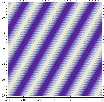
the relationship between the angle of incidence of the reference beam and the object beam and the fringe spacing is modeled using mathematica.
the fringe spacing when the angle between the 2 beams is
60degrees
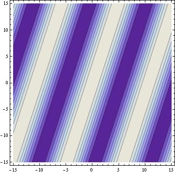
45degrees

36degrees
30degrees
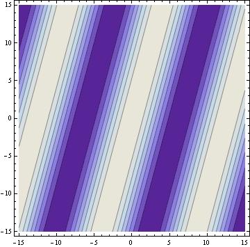
the mathematica models show that the fringe spacing is inversely related to the angle between the reference beam and the object beam.
d=(constant) wavelength/sinq
as a result of the fringe spacing, the frequency of the fringes is proportional to the angle and inversely proportional to the fringe distance.
f=C/d where C is a constant
Diffraction gratings have several uses. one of them is their use in atomic spectrometry. Knowledge of the fringe distance and frequency allows us to calculate the wavelengths of materials viewed through an atomic spectrometer. The quality of the lines in the spectrum depend on the resolution of the diffraction grating, which is influenced by the thickness of the films, the effectiveness of the development process and the quality of the gratings.

Mike,
It might be beneficial to explain a little more about what your findings mean relative to creating a hologram. Now that you’ve demonstrated that the relationship between the angle and the fringes, tell us what we can do with this knowledge.
Also, you mention how snell’s law is needed for holograms that are made on a thick plate, if we were creating a hologram with a thick plate, how would your results change?
Looks great otherwise.
Hey Michael. I enjoyed going through your findings. What struck me immediately was that there is a gradient of darkness for the dark fringes (because there are regions with partial destructive interference). I am curious to see how this affects the light that is diffracted by this type of grating. Maybe the diffraction pattern will not be as resolved as the diffraction pattern from a non-holographic grating. We could compare the patterns from a holographic and a non holographic grating during the demo you were thinking about doing !
Also, are these patterns based on the assumption that the path lengths of the two interfering beams are exactly the same? Is there a way to see how the diffraction pattern changes if the path length of one of the beam changes?
And finally, I came across this link which talks about circular holographic gratings:
http://adsabs.harvard.edu/abs/2002SPIE.4924..374H
I was wondering if you’d be able to model gratings with other shapes. Its just a thought…maybe that would require a very complicated code.
Anyway, thanks and good luck !
-Rahul