Category Archives: Tewa

Conclusion- Modeling the E and B Fields of A Cylinder

In the beginning, I set out to model the electric and magnetic field of any objects shaped like a cylinder. I wanted to demonstrate the direction and intensity for a conductor, a dielectric, and a coil. I did not get to model the E and B fields for all those different types of cylindrical objects, however I developed a method for modeling on mathematica. With the “Help” tab I was able to model the direction and intensity for a conducting cylinder.

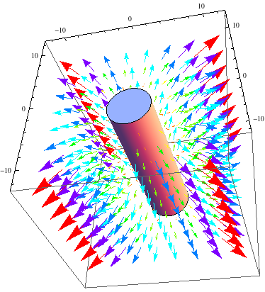
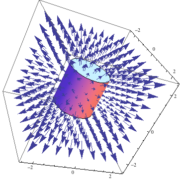
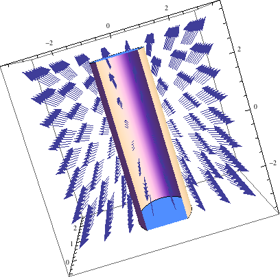
To find the electric field I chose to look at the E and B-fields of a long cylinder first, where this cylinder had a uniform charge density. Using Gauss’ Law I derived the E field (inside the long cylinder) and started looking at different functions on mathematica, to determine which one best demonstrated the direction and magnitude of the electric field. I first converted the coordinates from cylindrical to cartesian using the TransformedField function. After playing around with the VectorPlot and VectorPlot3D I was able to show (using the Show function) the electric field of a long cylinder. The E-field for the long cylinder, from my previous post, demonstrate the electric field within the long cylinder, where the electric field magnitude is directly proportional to the radius of the Gaussian cylinder. So, it makes sense that the arrows are getting thicker instead of shrinking in size.

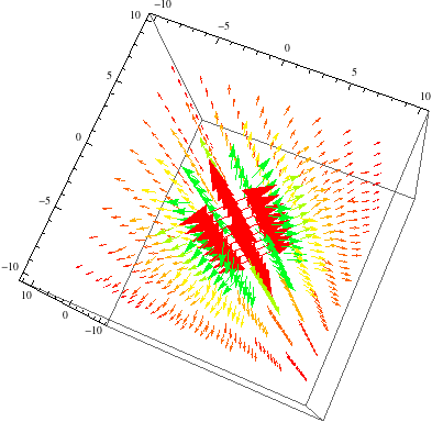
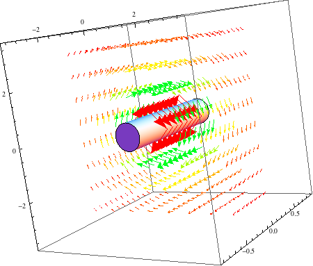
To find the magnetic field I also chose the same long cylinder, only this time, with a uniform current distributed on the surface of the cylinder. With this induced current flowing in the negative X direction, into the screen, I used the right hand rule to find that the magnetic field is in the positive phi direction. Using Ampere’s Law I came up with the equation for both inside and outside of the cylinder. As you can see in my previous post, the B-field equals zero inside of the cylinder and the B-field outside is inversely proportional to the radius of the cylinder. This is so because all of the current is on the surface of the long cylinder and as you move further away from long cylinder the intensity decreases.

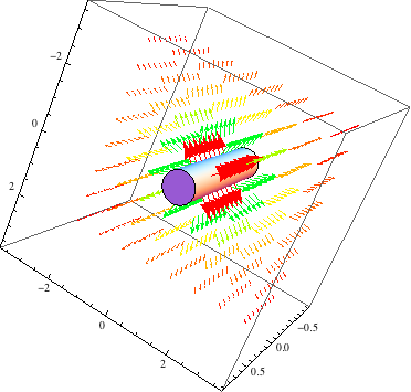
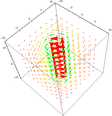
I then used the same procedures, kept the charge density for the E-Field and uniform current for the B-field the same. However, the equations are different now because of the parameters I placed on the finite cylinder. This cylinder has a length of 30cm with a radius of 10cm. After putting that into mathematica, similar results to the long cylinder were produced.

My main focus for this project was to learn how to use mathematica because deriving the E and B fields for a cylinder are things we learn in class. Mathematica is frustrating at first but after figuring out the proper functions I was able to model what we learn in class.


Share

Final Models(Updated)

Magnetic Field for a Cylindrical Conductor:

LONG CYLINDER:

Using Ampere’s Law I derived the magnetic field for a simple system, a long cylinder with the current uniformly distributed on its surface. Using Eq. 2, I was able to solve for the magnetic field. The results are as follows:

A) For s < r,       B=0

B) For s > r,                                                                                  (1)

                                                          (2)

 In Figure 1 , we have a ContourPlot of the magnetic field of a long cylinder with a current I distributed on the surface of the cylinder. Assuming that the current is flowing into the screen we know that the magnetic field is in the positive ϕ direction. If the current were coming out towards us, the magnetic field would be in the negative phi direction.

bfield4

Figure 1. This is a 2D contour plot that shows the flow of the B-field outside of the long cylinder. Look at this as if you were looking down on the cylinder with the current flowing into the screen. 

bfield2


Figure 2. Is another way of demonstrating what is happening to the long cylinder. This picture depicts the gradual decrease of the magnetic field’s magnitude as we move away further . The arrow curving around the top of the cylinder represents the direction of the B-field when the current is going into the screen.

Methods:

Using mathematica I was able to demonstrate these physical occurrences. Before developing the above figures I tried showing the magnetic field using the StreamPlot function, however that resulted in an oval like shape for the positive ϕ direction. The arrows are pointing in the right direction but the pattern formed does not represent the magnetic field for our situation. As you can see in Figure 3, the center of the plot starts of as a circle but as the radius of the cylinder increased the stream looses it’s circular shape and starts to flow like an ellipse.

streamplot


Figure 3. This is a StreamPlot of the B-Field outside of the long cylinder. This is not a correct illustration of what is happening to the wire because it’s shaped like an ellipse. 

Before entering my results into mathematica I changed from cylindrical coordinates to Cartesian coordinates using the TransformedField function. With this, my results are now

Similar methods were used for the electric field.

Electric Field for a long cylinder:

Using Guass’ Law I derived the electric field inside of a long wire with charge density , for some constant k. Using Equation 2, I got the equation   .

                                                                               (2)

With this I modeled Figure 4, where the vectors point radially outwards of the cylinder. Figure 4, illustrates what happens in the center of the wire.

efield2


Figure 4. This is the Gaussian cylinder within an actual cylinder, where the magnitude of the E-field increases as the Gaussian cylinder approaches the size of the actual cylinder. Think of the axes as the parameters for the actual cylinder.                                                 


FINITE CYLINDER:

ELECTRIC FIELD FOR A FINITE CYLINDER:

After looking at the models for the long wire and talking to Professor Magnes about my blog I did modeling for an actual cylinder with parameters. For the E-field, the Cylinder is 30cm in length with a radius of 10cm. It has a charge density of , which is the same as the long wire, only now confined to certain limits.  After doing the math to find the E-field outside of the cylinder ( s > r ), I got

,

where the k is a constant (where k = 1),  is the length of the cylinder ( = 30cm),  is the length of the Gaussian cylinder ( = 40cm),  r is the radius of the Cylinder , and s is the radius of the Gaussian cylinder.

desktop


Figure 5. This is the E-field of a finite cylinder. As you can see here the magnitude of the E-field decreases the further you move away from the cylinder. 

efiledf


Figure 6. I placed the cylinder within the plain from Figure 5 to show the E-Field moving radially outward. I altered the size of the cylinder to have a better view of what’s going on. 

MAGNETIC FIELD FOR A FINITE CYLINDER:

Here’s the magnetic field for a finite cylinder, with the same parameters as the one for the E-field. This is a cylinder with a current distributed uniformly across the surface of the cylinder. For this cylinder, I made the current (I) equal to 1A. After using Ampere’s law I got the same results as that of equation 1 from above.

bfieldf       bfieldf2


Figure 7. The image on the left demonstrates the B-field of a cylinder. The image on the right shows the field on the left acting on a cylinder with set limits. 

In this mathematica file you will also find a ContourPlot3D of what’s happening with the B-field. This file also contains the work I did for a Finite Cylinder.

To view the work I did in mathematica click on this link for the Electric Field:https://drive.google.com/file/d/0B2VxS7Y5dxIHMTZxUEFyb21yZWM/edit?usp=sharing

To view the work I did in mathematica click on this link for the Magnetic Field: https://drive.google.com/file/d/0B2VxS7Y5dxIHU0wxOTRHY0ZxdjA/edit?usp=sharing


Share

Preliminary Data

Using Gauss’s Law for the Electric Field, I found the electric field for a conducting cylinder with a charge density

CodeCogsEqn .                                                               (Eq.1)

The end result is the equation

.                                                          (Eq.2)

With this, I was able to model the following.

Efield for conductors                                           (Figure 1)

Here is a photo of what is occurring on the inside of the cylinder. As you can see in Figure 2, the Gaussian surface would be placed in the center of the cylinder where the vector fields start and are directed radially outward.  As implied by Equation 2, the electric field is directly proportional to the radius of the cylinder.

efield inside                                            (Figure 2)

I am currently working on modeling the magnetic field.


Share

Project Plan: Modeling the E and B- fields of a Cylinder

Sources:

Introduction to Electrodynamics by David J. Griffiths

What am I Modeling:
I will be modeling the E and B fields for a simple cylinder and then I want to do the same thing for more complicated systems(i.e conductors, dielectrics, etc). I would love to finish my project by modeling the E and B fields for a coil.

Due Dates-
APRIL 14TH: Finish modeling the E and B Fields for a simple system
APRIL 21ST:Finish modeling for complex systems
APRIL 28TH: Finish modeling for coil
APRIL 29TH: Make sure that all animations work on my blog page
APRIL 30TH: Prepare my blog presentation
MAY 1ST: Submit final blog.

Collaborators:
I am collaborating with Ramy Abbady and Brian Deer. We have weekly meetings to talk about ways we could help each other and what we should expect the final product to be.

Share

E and M Spring Project

Our project for this course is Modeling electric and magnetic fields of a bar magnet, a cylinder, and a sphere using mathematica. I will be modeling the electric and magnetic fields for a cylinder. After developing a model for a general cylinder, I plan on modeling the electric and magnetic fields for different types of cylindrically shaped matter. This includes conductors and dielectrics. I would also like to do this for items with different current levels and to also model the magnetic field for different magnets (paramagnets, diamagnets, and ferromagnets). With this, I want to create a model for more complex systems, such as solenoids.

Share