Here is a link to the Mathematica script that has my graphs and animations used in this blog https://vspace.vassar.edu/brrachmilowitz/Graphs%26Pictures.nb


Here is a link to the Mathematica script that has my graphs and animations used in this blog https://vspace.vassar.edu/brrachmilowitz/Graphs%26Pictures.nb
I think it is important to talk a bit about the applications of an electro optic modulator. I think some of the modulation applications are fairly obvious. For example, phase modulation is useful when it comes to controlling what time and at what point in its oscillation a light wave will arrive somewhere. Also similar to phase modulation amplitude modulation allows for the control of the intensity.
The main perk of using an EoM as opposed to other less expensive optical elements is the ability to make the voltage time dependent or give it a frequency. The ability to turn the EoM on and off at rapid rates makes for some interesting applications.
One application I am most familiar with is the use of the polarization modulation to pulse a laser beam as shown below
Because of the rapid rate of turning on and off the EoM you get a laser coming out of it that is made up of alternating segments of horizontal and vertical polarization. After you send it through a polarizing beam splitter cube you get two pulsing laser beams.
The length of the pulses is directly proportional to the rate at which you turn the EoM on and off or the frequency which is the amount of times you turn it on in one second. To determine the pulse distance we can use this equation
(1) 
Where c is the speed of light and f is the frequency at of the EoM
This is very useful to obtain time resolution and filter out noise. Let’s say you have an event that happens in a material and you wish to study it with a laser. If you pulse the laser beam at a known frequency then you are able to only look at events that are happening during the time you know the laser is affecting the material. Like wise you are able to see when it is not affecting the material at the same frequency. This allows you to see events that happen for only a short moment of time within a material.
If I had more time in this project I would do an experimental side, where I use a real EoM to learn more about them. One of the things i would do is determine the size of the crystal inside the EoM by using the phase shift and the known index of refraction. I would also like to assemble the various beam map set ups i came up with In this project and see how effective they are in modulating the laser.
Inside an Electro optic modulator is a birefringent crystal. One of the more popular crystals to be used in EoMs are lithium niobate ( ) doped with magnesium oxide (MgO). The magnesium oxide is there to prevent optical damage that can occur with high energy light in the bluish green frequencies. The Index of refraction of this crystal is
  = 2.29 and the linear electro optic coefficient r = 30.9. I could not find any information on R the quadratic electro optic coefficient. Inside the EoM, the crystal has a parallel plate capacitor across it as shown below.

This capacitor allows for a voltage controlled uniform electric field. There is a well-known simple relationship
(1) 
Where V is the voltage d is the distance between the plates and E is the electric field strength which points from the positive to negative plate. This gives us a direct relationship between the electric field and the applied voltage. This can be used in determining required voltage to obtain specific types of modulations.
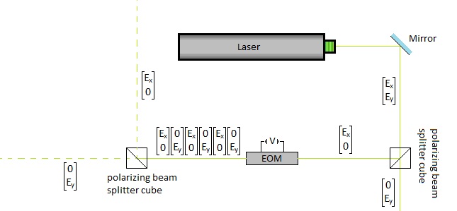
Amplitude modulation is very similar to phase modulation. In all previous types of modulation we split the beam up into two different oppositely polarized beams only to use one in the modulation process. In the case of amplitude modulation we still only send one beam through the EoM, but we are still in need of the second beam. The set up for amplitude modulation can be seen below.

In this set up there is a half wave plate to change the direction of the polarization of the laser beam entering the EoM to be identical to the one not going into the EoM. The EoM is used to modulate the phase of the beam exiting it. There are two polarizing beam splitter cubes that are used as one-way mirrors so the two beams can be joined back together. Being able to change the phase of one of the beams allows you to control how much constructive interference and how much destructive interference occurs when the beams add together as shown in the animation below.
The blue wave is the laser beam that is not going through the EoM, the red wave is the beam that is having its phase modulated from 0 to  as it passes through the EoM. The yellow wave is resultant amplitude modulation.
As you can see from the animation you are able to control the amplitude of the laser beam any where from 0 to twice the original amplitude.
The modulation of the polarization of a laser to me is the most interesting and applicable use of an EoM. I recall from before this equation
(1) 
This is the first key modulating the polarization this means once you give it the correct voltage to your EoM it acts like a half wave plate. A half wave plate is an optical element that that allows you to rotate your electromagnetic wave. The corresponding Jones matrix to this is  . I will go a little more in depth on different angles effects later on
Okay so before the laser enters the EoM it must be either horizontally or vertically polarized using some kind of polarizer. For example the use of the beam splitter in the figure below

Let’s use the horizontally polarized beam to be the one to go into the EoM so the Jones vector is  and lets orient the EoM to
  making the half wave plate Jones matrix
  so the effect looks like this

Notice the  is now in the y direction making the laser beam vertically polarized
Lets look at how a half wave plate acts for different  . Below is a graph of the amount of , the blue line and the amount of
  , the red line that will exit the half wave plate as a function of

As you can see that when  you have only a predicted above. From this graph you can also see that when
  you have equal amounts and
Here is an animation of How the electric field direction will change with different
Mathmatica was giving me a lot of trouble to do this simple task. This still shows how there exists a that will make the electric field switch directions
Phase modulation is not a very difficult concept to grasp. In my blog proposal I presented this equation
(1) 
This allows you to change the index of refraction with an applied electric field. The speed a wave travels inside a new medium is equal to the speed of light in a vacuum divided by the index of refraction of the material  . Using this relationship and the equation above, we have an expression that relates the applied electric field strength to the speed of the wave in inside the crystal.
(2) 
Once the wave exits the EoM it will have a shift in phase. Being able to vary the speed of the laser inside the crystal very slightly will give you the ability to modulate the phase of the laser so that you can have it exit the EoM at what ever point in its oscillation you wish.
Here is an animation showing a light wave entering a crystal and slowing down having its phase shifted. I could not figure out how to draw lines on the graph but the crystal is from 0 to
.
I think it is important to have an introduction into Jones vectors and matrices. A Jones vector is when you represent the Electric field as such
(1) 
A Jones matrix is a 2 by 2 matrix that does some kind of operation on the Jones vector thereby transforming it. These Jones matrices vary depending on the optical element that your electromagnetic wave is traveling through. Some examples of Jones matrices
Horizontal Polarizer:

Vertical Polorizer:

Half wave plate:

is the angle that the half wave plate is oriented at. These Jones vectors will be useful in describing how the electromagnetic wave is polarized in the following posts
Before I go into any detail of the modulation of laser beams I think it is important to mention that you can obtain the full expression of an electromagnetic wave through just knowing how the electric field is behaving. The electric field is related to the magnetic field by
(1) 
Where  is the unit vector pointing in the direction of propagation.From this point on I will only talk about how the electric field is behaving.
This project is about investigating electro-optic modulators and therefore I will focus on three main categories, theory, the device itself and its applications.
Theory: I will look into the mathematics and the physics involved in the three different kinds of modulation, phase, amplitude and polarization. The equations involved will be studied from several different perspectives. I may include hand worked solutions as well as simulations or animations from Mathematica. The animations could involve light waves entering and exiting the EOM, or before and after animations of what the electro magnetic wave looks like before and after modulation. Two equations I found that will be interesting to investigate are one relating electric field strength to induced index of refraction:
(1)
where  is the index of refraction with no present electric field, r and R are constants that are dependent on the crystal. Another equation allows the EoM to function as a half wave plate once a specific voltage is applied.
(2)
This equation is the key to modulating polarization of the laser beam.
Actual Device: Here I will investigate the electro-optic modulator itself. I will talk about what the device consists of, possibly making a picture with labels of the different components of the inside of one of these devices and go into the physics of the crystal itself. Here is where I will go into some detail about the electro-optic effect and piezoelectricity. Examples of devices and their properties will be given, most likely from companies that manufacture them for research purposes. I will also talk about the physical mechanism behind the piezo-electric effect within the crystal. The device that produces the effect is some kind of very high frequency voltage generator.
Applications: In this section I will look into a few applications of electro-optic modulators. I want to find an application for each kind of modulation. I will discuss why an experimentalist would be interested in doing the different kinds of modulations and why it is useful. I may be able to find some recent data from a published paper that used one of these devices.
An electro optic modulator is a device that contains some kind of material that displays the electro optic effect. This means something inside this device, most likely a crystal of some kind has its optical properties change when a voltage is applied across it. This change in the crystal allows the laser beam traveling through it to also change “modulating it”. This modulation can change things such as amplitude and phase among other things. My project is going to be investigating into how an electro optic modulator works.
Social Widgets powered by AB-WebLog.com.