
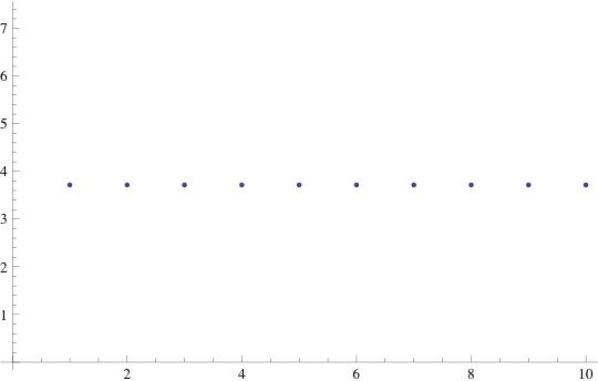
Having been stymied by the constraints that mathematica imposes on integrals of absolute value functions, I have forgone my attempt to create a smooth plot and moved on to obtaining discrete values and using them to create my plot. Plotting the difference in rotation frequency between rotor and stator vs the the total induced emf produced by a single rotation, I have made a surprising discovery. In my model, it does not seem to matter what I make the rotation rate: the emf induced remains constant. The plot below gives values 1-10 for $\Delta \omega$ with corresponding values for $\epsilon_{induced}$.
Another oddity that comes to our notice is that our expression for $n$ plays exactly the same role in this equation as $\Delta \omega$. That is to say, increasing the number of wire coils achieves the same objective as increasing the rotation rate of the rotor.
This is very interesting indeed, and quite handy as well. A problem with some wind turbine designs (fixed-pitch, for example) is that they function suboptimally at lower rotation rates. This causes a certain amount of inherent inefficiency in the generator (or rather adds to the inefficiency already present). My model, while far from perfect, suggests that this might be ameliorated by increasing the number of wire loops in the stator. As this inefficiency is largely a problem in cheaper turbine designs, it is my hope that this technique (being relatively inexpensive) may offer a cost-effective way to improve efficiency.
As in the last post, the mathematica code for the above can be found in
https://vspace.vassar.edu/xythoswfs/webview/fileManager.action?entryName=/jamcentire&stk=A6745A2F45FA75A&msgStatus=3%20documents%20have%20been%20successfully%20uploaded%20to%20the%20folder%2C%20jamcentire.
